Real-time monitoring system for structural micro-deformation based on laser range finder

A real-time monitoring system and laser rangefinder technology, which are applied in the field of building monitoring to achieve the effects of improving measurement accuracy, reducing measurement errors, and being easy to install.

Active Publication Date: 2019-07-12
上海潮旅信息科技有限公司
View PDF7 Cites 7 Cited by
  • Summary
  • Abstract
  • Description
  • Claims
  • Application Information

AI Technical Summary

Problems solved by technology

[0005] In order to overcome the above-mentioned defects of the prior art, an embodiment of the present invention provides a real-time monitoring system for structural micro-deformation based on a laser rangefinder, through marking points A, B, C and D in conjunction with a laser rangefinder and a leveling instrument, Long-distance monitoring of micro-deformation of buildings, easy installation, no need to touch the measured object, avoiding the phenomenon of building damage, real-time monitoring of the measured object, considering the impact of laser rangefinder settlement on the measurement results, reducing measurement errors, using The value obtained by the electronic level measuring instrument is more accurate, the measurement accuracy is improved, and the deformation is calculated to visualize the data

Method used


Image

  • Real-time monitoring system for structural micro-deformation based on laser range finder
  • Real-time monitoring system for structural micro-deformation based on laser range finder
  • Real-time monitoring system for structural micro-deformation based on laser range finder

Examples


Embodiment Construction

[0043] The following will clearly and completely describe the technical solutions in the embodiments of the present invention with reference to the accompanying drawings in the embodiments of the present invention. Obviously, the described embodiments are only some, not all, embodiments of the present invention. Based on the embodiments of the present invention, all other embodiments obtained by persons of ordinary skill in the art without making creative efforts belong to the protection scope of the present invention.

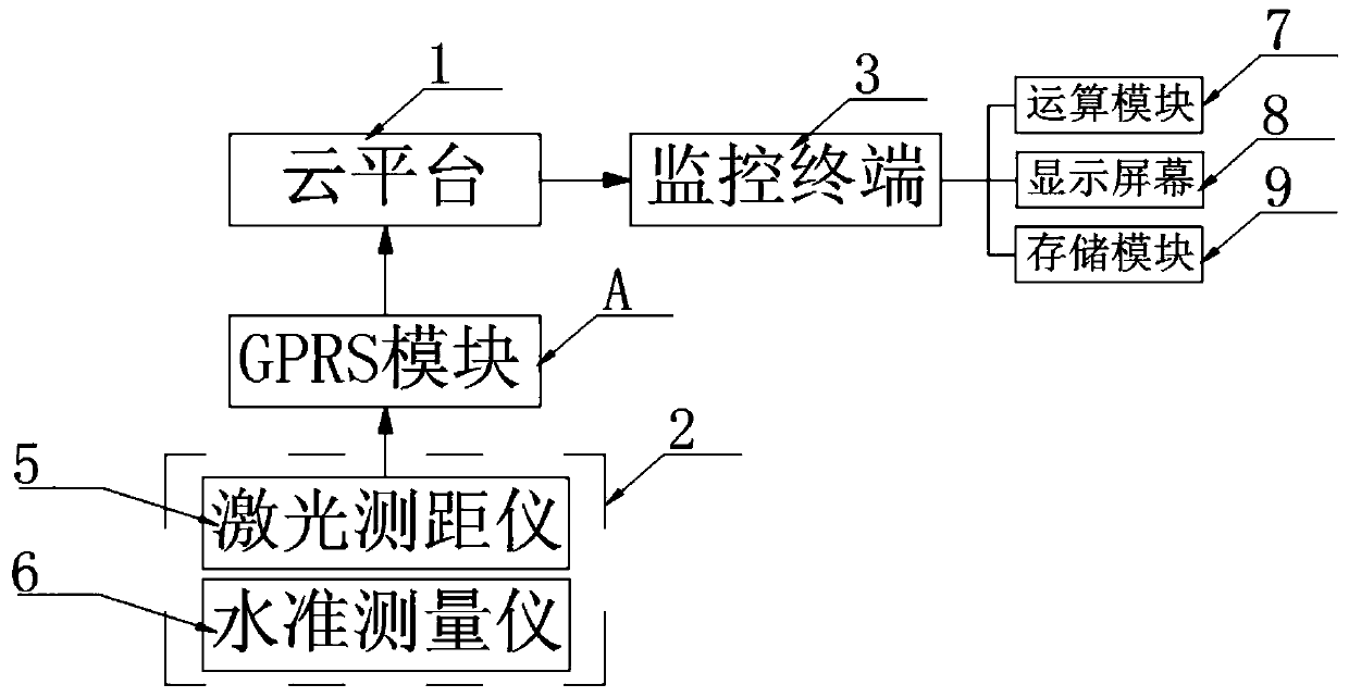
[0044] according to Figure 1-6 A kind of structural micro-deformation real-time monitoring system based on the laser range finder as shown, comprises cloud platform 1, is characterized in that: the input end of described cloud platform 1 is provided with monitoring system 2, and the output end of described cloud platform 1 is provided with There is a monitoring terminal 3, and the connection end of the monitoring system 2 is provided with a GPRS module 4;

...


PUM


Abstract

The invention discloses a real-time monitoring system for structural micro-deformation based on a laser range finder, and particularly relates to the field of building monitoring. The system comprisesa cloud platform, wherein the input end of the cloud platform is provided with a monitoring system, the output end of the cloud platform is provided with a monitoring terminal, the connection end ofthe monitoring system is provided with a GPRS module, the monitoring system comprises a laser range finder and a level measuring instrument, and the level measuring instrument is disposed on one sideof the laser range finder. The real-time monitoring system cooperates with the laser range finder and the level measuring instrument by marking points A, B, C and D to remotely monitor the micro-deformation of the building, is convenient to install without contacting the object to be measured to avoid the phenomenon that the building is damaged, real-time monitors the measured object, considers the influence of the laser range finder on the measurement result, reduces the measurement error, makes the value obtained by the electronic level measuring instrument more accurate, improves the measurement precision accurately, and calculates the deformation amount to make the data visual.

Description

technical field [0001] The invention relates to the field of building monitoring, and more specifically, the invention relates to a real-time monitoring system for structural micro-deformation based on a laser range finder. Background technique [0002] Structural safety monitoring mainly includes deformation monitoring, seepage monitoring, stress and strain monitoring, temperature monitoring, etc. Among them, deformation monitoring is intuitive and reliable, and can basically reflect the structural safety behavior under various loads, so it has become the most important monitoring item. The present invention is primarily concerned with structural surface deformation. At present, the structural surface deformation monitoring technology mainly includes: conventional geodetic surveying technology, measuring robot monitoring technology, ground three-dimensional laser scanning technology, photogrammetry and remote sensing technology, GPS technology, etc. [0003] Conventional ...

Claims


Application Information

Patent Timeline
Patent Type & Authority Applications(China)
IPC IPC(8): G01B11/16G01C5/00
CPCG01B11/16G01C5/00
Inventor 陈勇李晓武向南付焕平刘青麟
Owner 上海潮旅信息科技有限公司
Why Eureka
Try Eureka