
A ground radar antenna reflector

A technology of radar antennas and reflectors, which is applied in the direction of antennas and electrical components, can solve the problems of poor maneuverability, large antenna array structure size, and large array aperture, so as to overcome gravity and external wind loads, deploy and disassemble The closing speed is fast, reducing the effect of swinging left and right

Active Publication Date: 2020-09-01
合肥开泰机电科技有限公司 +1
View PDF9 Cites 0 Cited by
  • Summary
  • Abstract
  • Description
  • Claims
  • Application Information

AI Technical Summary

Problems solved by technology

In practice, for large-caliber ground radars, the size of the antenna array structure is large, and there are many transport units. The dismantling work often takes more than a dozen people and several hours to complete. It is very difficult to transfer and re-erect, and the mobility is poor.
[0003] If the current ground radar antenna uses high-strength steel as the truss material of the planar array radar antenna, although it can effectively improve the rigidity of the array, it also increases the weight of the antenna, reduces the efficiency of dismantling and erection, and affects the maneuverability of the whole machine. Sexually affected
In addition, due to the large diameter of the array, the transportation of the antenna needs to be assembled, spliced ​​and transported in pieces, and the manual disassembly process is time-consuming and laborious

Method used


Image

  • A ground radar antenna reflector
  • A ground radar antenna reflector
  • A ground radar antenna reflector

Examples


Embodiment Construction

[0023] The technical solutions in the embodiments of the present invention will be clearly and completely described below in conjunction with the embodiments of the present invention. Apparently, the described embodiments are only some of the embodiments of the present invention, not all of them. Based on the embodiments of the present invention, all other embodiments obtained by persons of ordinary skill in the art without creative efforts fall within the protection scope of the present invention.

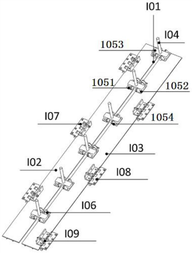
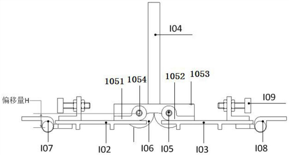
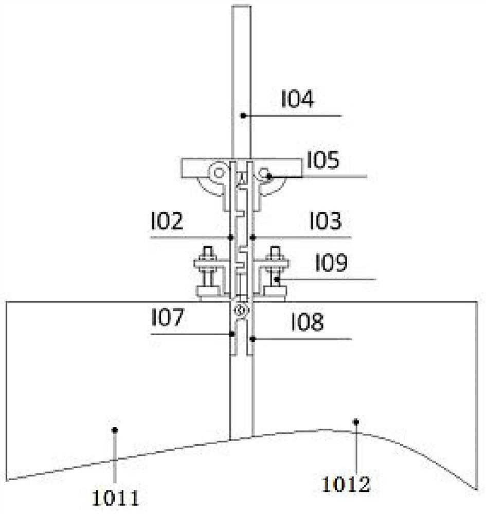
[0024] Such as Figure 1-4 As shown, the reflector main body 101 adopts the folding method to realize rapid deployment and disassembly of the antenna, and the reflector main body 101 needs to meet the following conditions during design:

[0025] S1: After unfolding, the reflective surface of the main body 101 of the reflecting plate should be flush with the upper surfaces of the left connecting rod 1011 and the right connecting rod 1012 and be in good electrical contact with the l...


PUM


Abstract

The invention discloses a ground radar antenna reflecting plate, which comprises a reflecting plate main body, wherein the reflecting plate main body is composed of a left block and a right block, theupper end of the left block is provided with a left hinge plate at the right side edge position, the upper end of the right block is provided with a right hinge plate at the left side edge position,and the upper ends of the left hinge plate and right hinge plate are provided with a limit plate. In the invention, the reflecting plate adopts an automatic folding technology, requirements of maneuvering performance indexes of radar complete vehicle are met, the unfolding and disassembling speed is high, the operation is convenient, the volume is compact after the disassembly, the transportationis facilitated, and the stability of the reflecting plate at the transportation state can be improved. Meanwhile, the interference generated between a radiation rod and other structural members, whichaffects the use, in the processing unfolding and folding process of the reflecting plate is prevented, the unfolding and folding between the left block and the right block on the reflecting plate adopts a movement mode with degrees of freedom, the influences of gravity and external wind load can be overcome, and the left block and the right block are synchronously folded and unfolded along with aleft connecting rod and a right connecting rod.

Description

technical field [0001] The invention belongs to the technical field of antennas, in particular to a ground radar antenna reflector. Background technique [0002] With the development of information warfare, vehicle-mounted radars with high maneuverability and suitable for field environments have become the main development direction of ground radars. With the increasing development of ground radar, its antenna is required to have the characteristics of large array aperture, large amount of equipment and heavy load. In practice, for large-caliber ground radars, the size of the antenna array structure is large, and there are many transportation units. The dismantling work often takes more than a dozen people and several hours to complete. It is very difficult to transfer and re-erect, and the mobility is poor. [0003] If the current ground radar antenna uses high-strength steel as the truss material of the planar array radar antenna, although it can effectively improve the r...

Claims


Application Information

Patent Timeline
Patent Type & Authority Patents(China)
IPC IPC(8): H01Q15/14
CPCH01Q15/14
Inventor 汪明刚赵承三陈建平孙艳龙许金玖
Owner 合肥开泰机电科技有限公司
Learn More