Reception device, antenna, and junction cable

a technology of junction cable and reception device, which is applied in the direction of antenna, antenna details, elongated active element feed, etc., can solve the problems of difficult to include the antenna in the reception device, the design of the reception device is compromised, and the configuration of the reception device becomes complicated, so as to achieve simple configuration, improve the effect of performance and fine design

Active Publication Date: 2008-10-16
SONY SEMICON SOLUTIONS CORP
View PDF12 Cites 16 Cited by
  • Summary
  • Abstract
  • Description
  • Claims
  • Application Information

AI Technical Summary

Benefits of technology

[0010]Accordingly, the present invention proposes an antenna achieved to be mechanically strong, finely designed, and high performance b...

Problems solved by technology

However, since the antennas are increased in size in an ultra-high-frequency (UHF) band and a very-high-frequency (VHF), it was difficult to include the antennas in the reception devices.
However, when the rod antenna is provided in the reception device, the configuration of the reception device becomes complicated.
Further, the rod antenna juts out the reception device so that the design of the reception device is compromised, for example.
Further, since various parts of the earphone cable are brought in contact with the human body, it has been difficult to make full use of functions of th...

Method used


Image

  • Reception device, antenna, and junction cable
  • Reception device, antenna, and junction cable
  • Reception device, antenna, and junction cable

Examples


first embodiment

(1) Configuration of First Embodiment

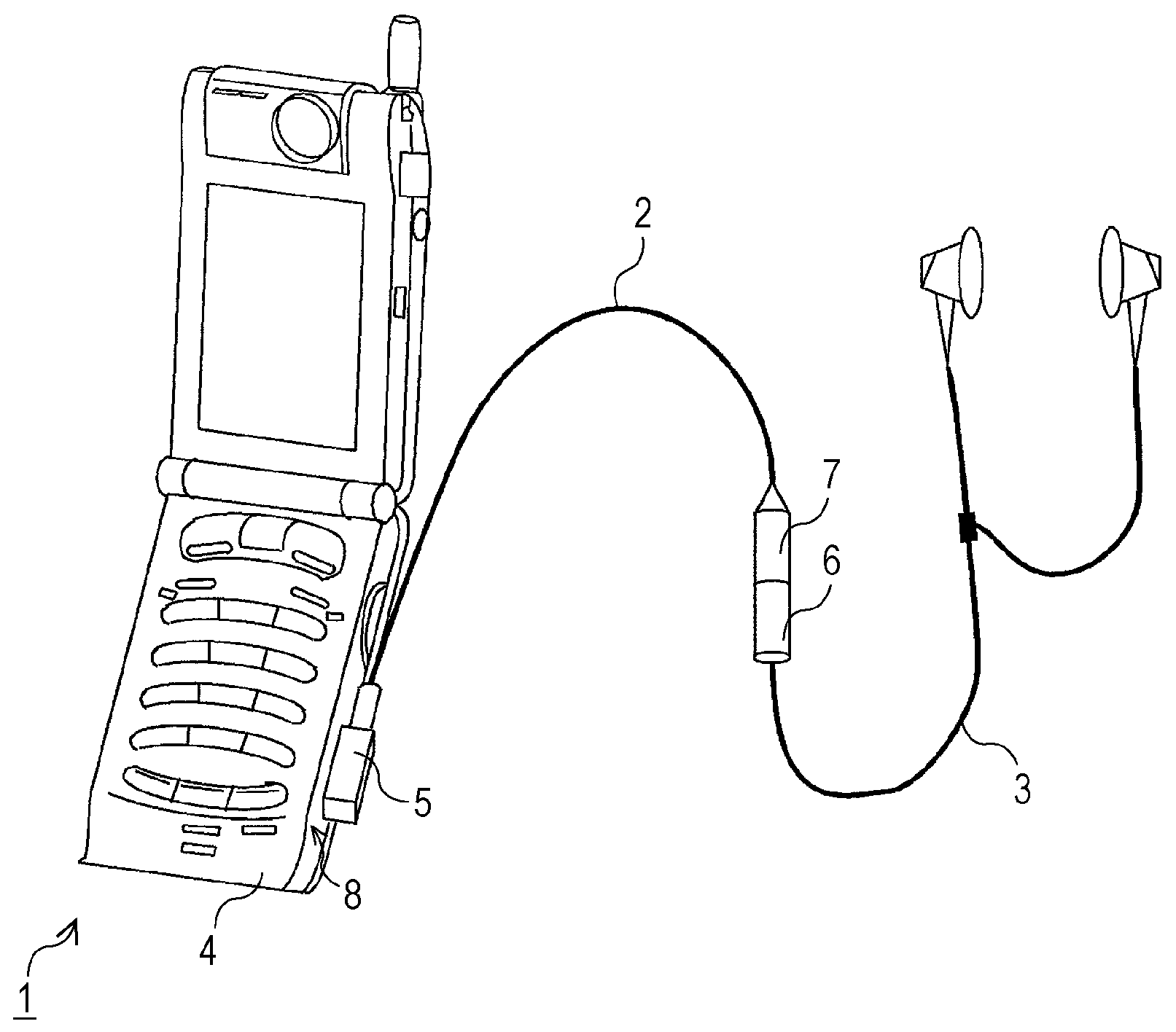
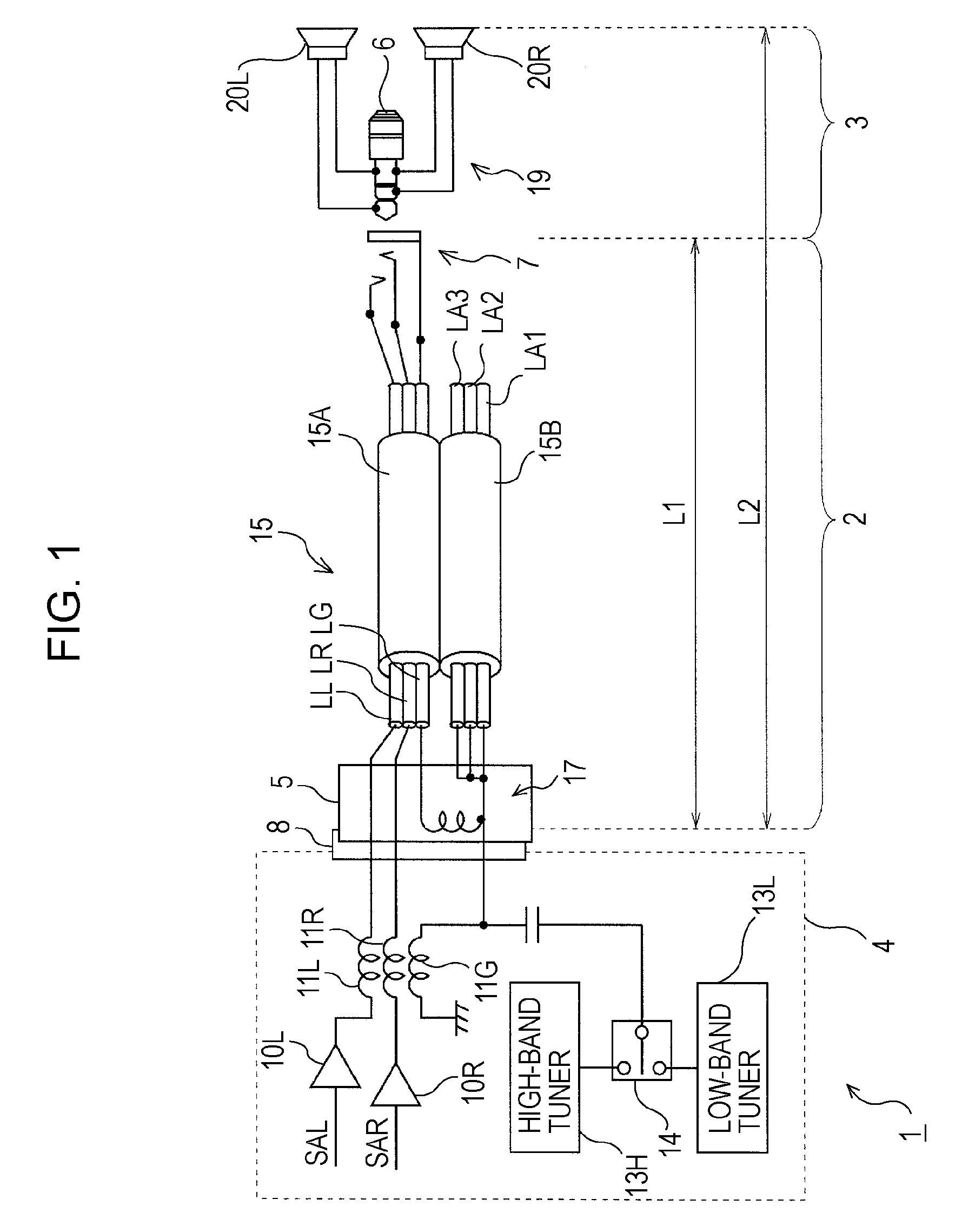
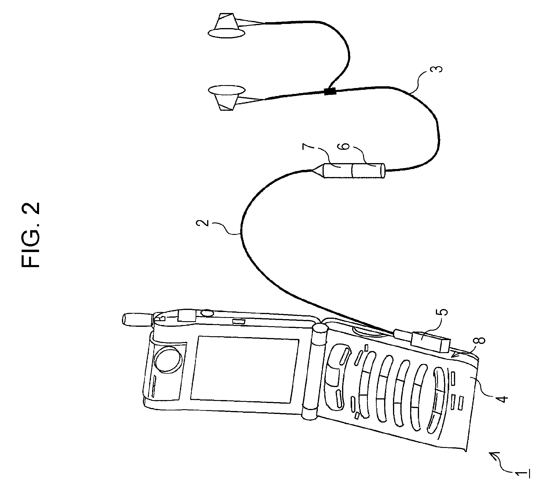
[0066]FIG. 1 is a block diagram showing part of a mobile-phone system 1, which is a reception device according to an embodiment of the present invention. FIG. 2 is a perspective illustration of the mobile-phone system 1. The mobile-phone system 1 has the function of receiving a radio broadcast. When a set of earphones 3 is connected to a main-body device 4 via a junction cable 2, the radio broadcast can be received by using the above-described junction cable 2 and the set of earphones 3, as an antenna.

[0067]Therefore, the junction cable 2 includes a plug 5 connected to the main-body device 4 on its main-body-device-4 side, and a jack 7 on the earphone-3 side, where a plug 6 of the set of earphones 3 is connected to the jack 7. For supporting the above-described configuration, the main-body device 4 includes a jack 8 to which the plug 5 of the junction cable 2 is connected.

[0068]Here, in the main-body device 4, an amplifier circuit 10L amplifies a...

second embodiment

[0101]According to a second embodiment of the present invention, a ground line is specifically designed and provided for each of audio signals of the left and right channels. Therefore, the first and second stranded-wire parts are formed, where each of the stranded-wire parts includes four cables. As for the second stranded-wire part, ends of the four cables thereof are grouped on the main-body-device side and connected to the plug 5. As for the first stranded-wire part, at least one of the ground lines specifically designed for the audio signals is connected to the cables of the second stranded-wire part.

[0102]Although the specifically designed ground line is provided for each of the right and left channels, as in the second embodiment, the same effects as those of the first embodiment can be obtained.

third embodiment

[0103]FIG. 18 is a schematic diagram showing a junction cable 33 used in a third embodiment of the present invention. The junction cable 33 and a set of earphones connected to the jack 7 form a headset. Further, on one of ends of the junction cable 33, the end being provided on the jack-7 side, a microphone 35 and a switch circuit 36 used to remotely control a main-body device are provided. For supporting the above-described configuration, each of the first and second stranded-wire parts 15A and 15B includes five cables. In the junction cable 33, ends of the five cables of the second stranded-wire part 15B, the ends being provided on the main-body-device side, are grouped and connected to the plug 5. Further, in the first stranded-wire part 15A, the ground line is connected to the cable of the second stranded-wire part 15B.

[0104]If a microphone, a switch circuit, etc. are provided, as in the above-described embodiment, the same effects as those of the first embodiment can be obtaine...


PUM


Abstract

A reception device including a transmission part having transmission cables transmitting a signal and/or power of a main-body device, an antenna part provided along the transmission cables from main-body-device-side ends of the transmission cables to a point between the main-body-device-side ends and the other ends of the transmission cables so that a high-frequency-signal-transmission path is formed, a high-frequency-elimination circuit provided at the main-body-device-side ends, which eliminates entry of the high-frequency signal to the main-body device, and a tuner that connects one of ends of the antenna part, the end being provided on the main-body-device side, to an antenna-input terminal and that receives a broadcast wave falling within the first frequency band corresponding to the antenna part's length is provided. The other end of the antenna part is an open end.

Description

CROSS REFERENCES TO RELATED APPLICATIONS[0001]The present invention contains subject matter related to Japanese Patent Application JP 2007-104112 filed in the Japanese Patent Office on Apr. 11, 2007 and Japanese Patent Application JP 2007-106810 filed in the Japanese Patent Office on Apr. 16, 2007, the entire contents of which are incorporated herein by reference.BACKGROUND OF THE INVENTION[0002]1. Field of the Invention[0003]The present invention relates to a reception device, an antenna, and a junction cable and can be used for a mobile-phone system that can receive a digital-radio broadcast, etc. According to the present invention, one of sides of a path provided to transmit a high-frequency signal is used as an antenna ready for a specified frequency band, the side extending from a main-body device to a predetermined point, and the other side of the path is assigned as a path provided to transmit an audio signal, etc., so that an antenna achieved to be mechanically strong, finel...

Claims


Application Information

Patent Timeline
IPC IPC(8): H04M1/00
CPCH01Q1/273H01Q9/30H01Q9/40
Inventor MUKAI, KOICHIYOSHINO, YOSHITAKAKOMORI, CHISATO
Owner SONY SEMICON SOLUTIONS CORP
Why Eureka
Try Eureka