
Live-line wire lapping operation device for J-type wire clamp and application method

A technology of operating device and wire clip, which is applied in the direction of wire winding connector, clip connection conductor connection, etc., which can solve the problems of easy occurrence of phase-to-phase or phase-to-ground short circuit, short distance of grounding body, multiple contact of main wire with double-ended wire clip at the source, etc. problems, to achieve the effect of improving assembly accuracy and assembly efficiency, improving assembly accuracy, and simplifying the operation process

Pending Publication Date: 2019-07-12
YIJIAHE TECH CO LTD
View PDF0 Cites 5 Cited by
  • Summary
  • Abstract
  • Description
  • Claims
  • Application Information

AI Technical Summary

Problems solved by technology

However, the traditional live lap leads have the following hidden dangers: 1) When using the original double-ended wire clamp live lap lead, because the end of the branch lead wire needs to be adjusted by 90°, the double-ended wire clip at the source will contact the main wire multiple times. ;2) Because the opening direction of the end of the branch wire clamp does not match the connection direction of the main wire, the distance between the branch wire and the live lead wire of the adjacent phase and the grounding body is too close, which is prone to phase-to-phase or phase-to-ground short circuit accidents

Method used


Image

  • Live-line wire lapping operation device for J-type wire clamp and application method
  • Live-line wire lapping operation device for J-type wire clamp and application method
  • Live-line wire lapping operation device for J-type wire clamp and application method

Examples


Embodiment Construction

[0033] In order to make the purpose, technical solution and advantages of the present invention clearer, a J-type wire clamp electric lap wire operating device of the present invention will be described in further detail below in conjunction with the accompanying drawings and embodiments; it should be understood that the The specific examples are only used to explain the present invention, not to limit the present invention.

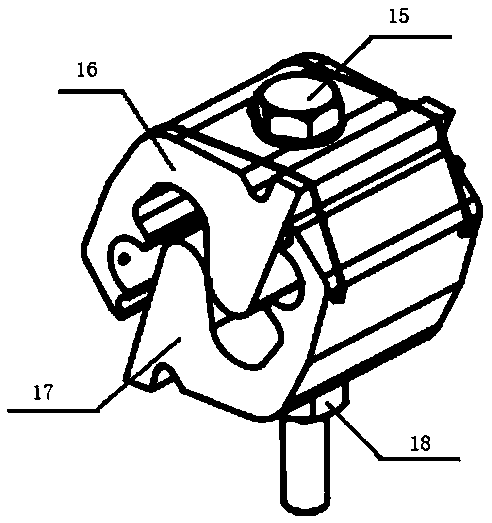
[0034] figure 1 Shown is a schematic diagram of the structure of the J-shaped wire clamp, which is a prior art and is not included in the protection scope of the present invention.

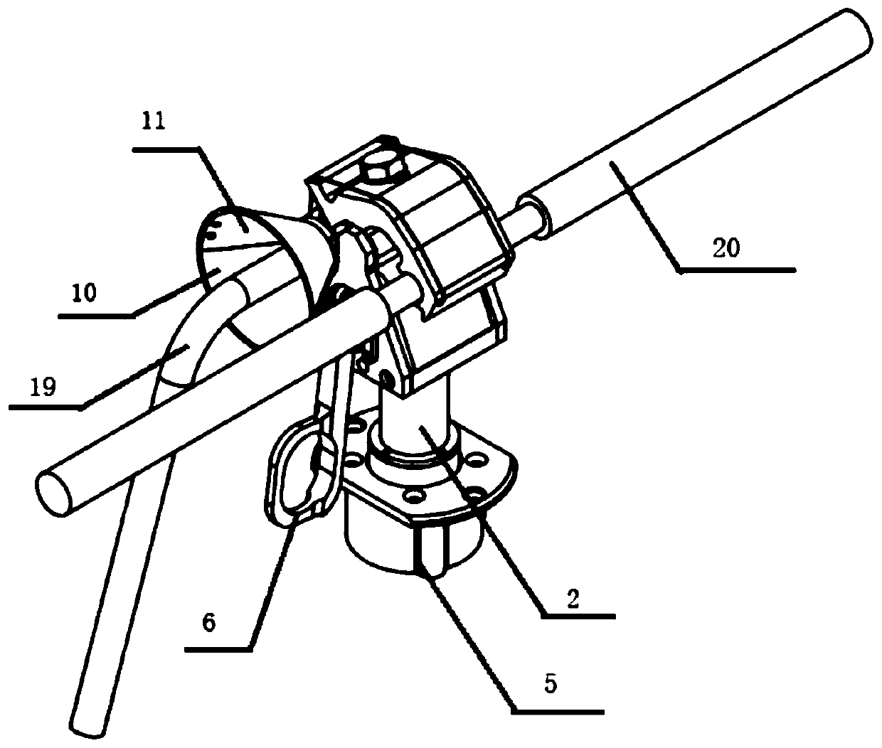
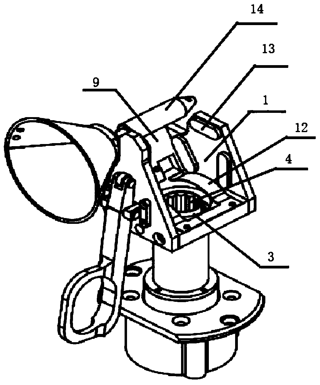
[0035] Such as Figure 2 to Figure 6 As shown, a J-type wire clamp with electric lap wire operating device of the present invention includes a J-type wire clamp, a support seat 1 for supporting the J-type wire clamp, a support sleeve 2 and a wire clamp driving shaft 3, and the wire clamp driving shaft 3. The upper part is provided with a nut groove 4, and the lower part of...


PUM


Abstract

The invention discloses a live-line wire lapping operation device for a J-type wire clamp and an application method. The live-line wire lapping operation device comprises a J-type wire clamp, a support base used for supporting the J-type wire clamp and a support sleeve, and further comprises a wire clamp driving shaft, wherein the support base is fixed on the upper part of the support sleeve, thewire clamp driving shaft is rotatably installed in the support sleeve, the upper part of the wire clamp driving shaft is provided with a nut groove with the opening facing upward, the nut groove is used for placing a driving nut of the J-type wire clamp, the lower part of the wire clamp driving shaft is provided with a driving device, and the driving device can drive the wire clamp driving shaft to rotate. The device disclosed by the invention realizes a live-line lapping operation of the J-type wire clamp, and the wire clamp drive is post-positioned so as to avoid the electric shock damage ofa high-voltage wire to low-voltage drive. The live-line wire lapping operation device has the advantages of high efficiency, simple operation and convenient disassembly.

Description

technical field [0001] The invention relates to the field of electric power construction equipment, in particular to a J-shaped wire clamp live lap wire operating device and a using method. Background technique [0002] The general method of using the original double-headed clamp "live lap lead" is: the operator first adjusts the end of the branch lead by 90°; the branch lead is connected to one end of the double-ended clamp; The clamp is lapped with the overhead main line and the clamp is fixed with a tool; the lap is completed. However, the traditional live lap leads have the following hidden dangers: 1) When using the original double-ended wire clamp live lap lead, because the end of the branch lead wire needs to be adjusted by 90°, the double-ended wire clip at the source will contact the main wire multiple times. ; 2) Because the opening direction of the end of the branch line does not match the connection direction of the main lead wire, the distance between the branc...

Claims


Application Information

Patent Timeline
IPC IPC(8): H01R11/15H01R43/027
CPCH01R11/15H01R43/027
Inventor 蔡海晨郭强张大伟曲谛李栗
Owner YIJIAHE TECH CO LTD
Learn More