Oil collecting device

A technology for oil collection and oil collection pipe, which is applied in liquid separation, chemical instruments and methods, and immiscible liquid separation, etc. It can solve the problems of air pollution, odor-dissipating bacterial growth, and cost a lot of manpower, material, and financial resources, and achieve high-efficiency oil and water. Separation, oil collection efficiency and high efficiency, the effect of efficient oil collection

Pending Publication Date: 2019-07-16
广州蒙太奇电器有限公司
View PDF7 Cites 7 Cited by
  • Summary
  • Abstract
  • Description
  • Claims
  • Application Information

AI Technical Summary

Problems solved by technology

Calculated on the basis of 0.8-1 kg per capita per day, the total amount of kitchen food waste generated in the country every day is as high as nearly 1.2-1.5 million tons! The front-end collection, clearing and transportation of such a large amount of kitchen food waste with extremely high water content not only consumes a lot of manpower, material and financial resources, but also inevitably causes urban sanitation and environmental problems such as odor emission, bacterial growth, and sewage splashing. , the back-end landfill or incineration will inevitably produce serious consequences such as air pollution, groundwater and soil pollution
[0003] The most important step when dealing with food waste is to collect the oil in the food waste. The existing oil collection methods cannot achieve high-efficiency oil collection and will collect a large amount of water, which cannot solve the problem of recycling food solid particle residues in the kitchen. high fat content

Method used


Image

  • Oil collecting device
  • Oil collecting device
  • Oil collecting device

Examples


Embodiment Construction

[0019] The present invention will be further described below in conjunction with accompanying drawing description and specific embodiment:

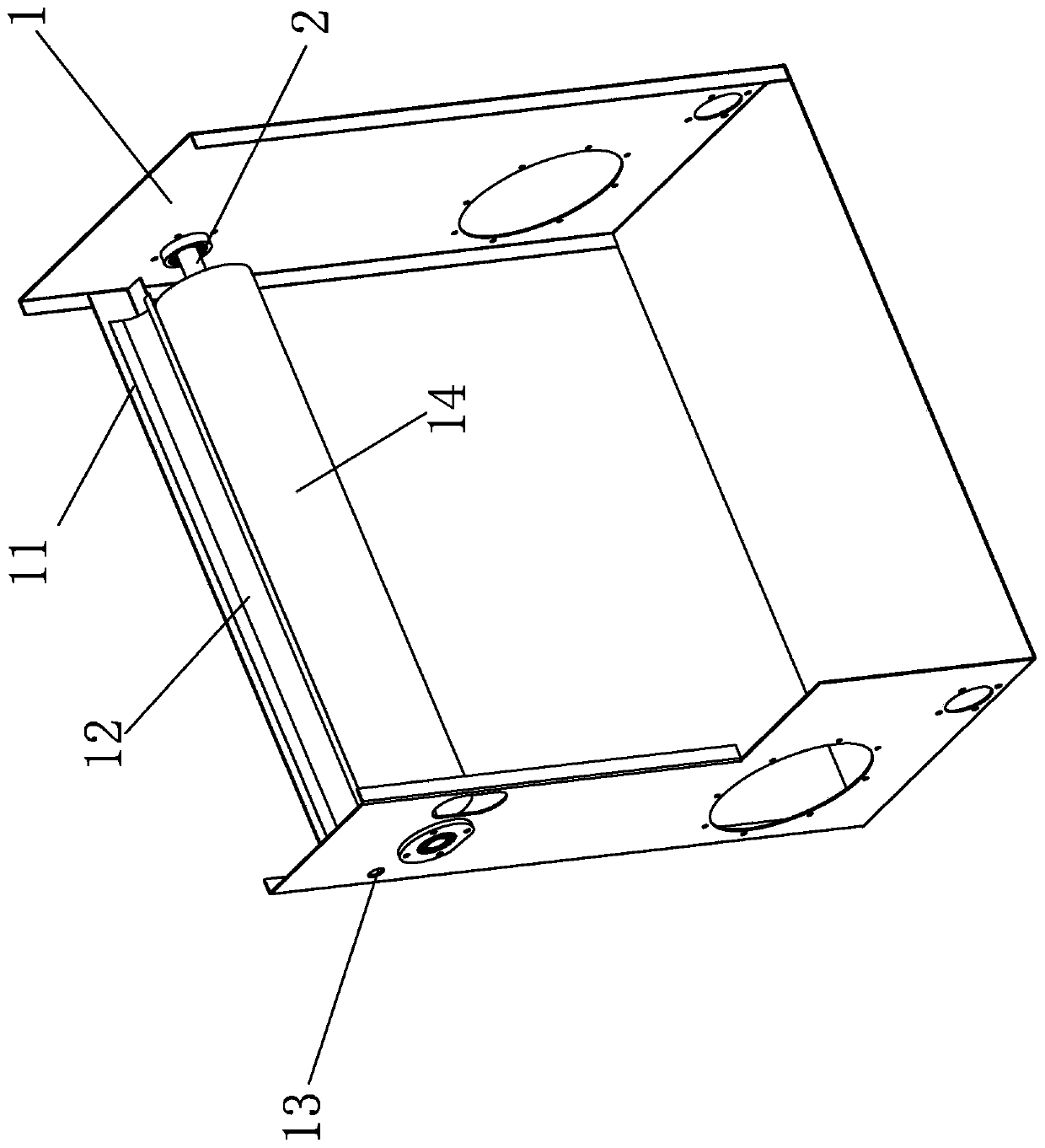
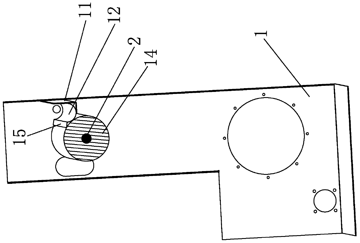
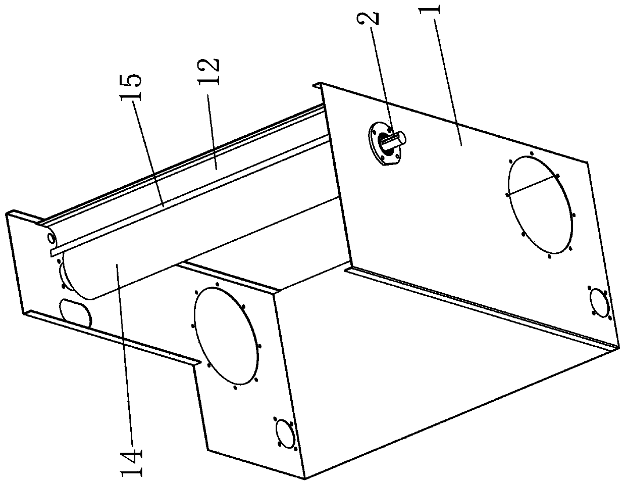
[0020] Such as Figures 1 to 5 As shown, the first embodiment of an oil collecting device includes a fixed frame 1, a rotating shaft 2 is inserted transversely on the fixed frame 1, an oil collecting roller 14 is arranged on the rotating shaft 2, and the oil collecting The fixed frame 1 on the rear side of the roller 14 is provided with a semi-arc oil collection pipe 12, and a scraper 15 is arranged on the side of the semi-arc oil collection pipe 12 close to the oil collection roller 14, and the scraper 15 is attached to the On the surface of the oil collection roller 14, the two ends of the semi-arc oil collection pipe 12 are attached to the fixed frame 1, and the fixed frame 1 on one side of the semi-arc oil collection pipe 12 is provided with an oil outlet 13. The semi-arc-shaped oil collection pipe 12 is inclined toward the oil outle...


PUM


Abstract

The invention discloses an oil collecting device. The oil collecting device comprises a fixed frame, wherein a rotating shaft is transversely inserted onto the fixed frame, an oil collecting rolling shaft is arranged on the rotating shaft, a half-arc-shaped oil collecting pipe is arranged on the fixed frame at the rear side of the oil collecting rolling shaft, a scraper is arranged at one side, close to the oil collecting rolling shaft, of the half-arc-shaped oil collecting pipe and is abutted against the surface of the oil collecting rolling shaft, the two ends of the half-arc-shaped oil collecting pipe are abutted against the fixed frame, an oil outlet is formed in the fixed frame at one side of the half-arc-shaped oil collecting pipe, and the half-arc-shaped oil collecting pipe is tilted towards the oil outlet side. Through the characteristic of stickiness of oil and rolling of the oil collecting rolling shaft on the surface of oily water, oil will be adsorbed to the surface of theoil collecting rolling shaft, the oil adsorbed to the surface of the oil collecting rolling shaft will be scraped off by the scraper when the oil collecting rolling shaft passes through the scraper during rotation, and then, the oil flows onto the half-arc-shaped oil collecting pipe and then is discharged through the oil outlet, so that efficient oil collecting is achieved, water is prevented frombeing collected during oil collecting, and efficient oil-water separation is achieved.

Description

technical field [0001] The invention relates to the field of food residue treatment, in particular to an oil collector. Background technique [0002] With the rapid development of the domestic economy and urbanization, the siege of garbage is becoming more and more embarrassing. Accounting for about 50% of the total amount of garbage, kitchen food waste is becoming a huge social problem. Calculated on the basis of 0.8-1 kg per capita per day, the total amount of kitchen food waste generated in the country every day is as high as nearly 1.2-1.5 million tons! The front-end collection, clearing and transportation of such a large amount of kitchen food waste with extremely high water content not only consumes a lot of manpower, material and financial resources, but also inevitably causes urban sanitation and environmental problems such as odor emission, bacterial growth, and sewage splashing. , The back-end landfill or incineration will inevitably produce serious consequences ...

Claims


Application Information

Patent Timeline
Patent Type & Authority Applications(China)
IPC IPC(8): B01D17/022
CPCB01D17/02
Inventor 敬华龙张华敬佰川敬依诺张芙嘉
Owner 广州蒙太奇电器有限公司
Why Eureka
Try Eureka