Casting factory double-disc cooler water adding device

A technology for cooling machines and foundries, which is applied to casting molding equipment, cleaning/processing machinery for casting mold materials, manufacturing tools, etc. It can solve the problem of loose installation of wear plates and buffer plates, poor filtering ability, and damage to buffer plates and other problems, to achieve the effect of convenient and effective cleaning, easy installation and reasonable structure

Inactive Publication Date: 2019-07-16
济南市平阴县玛钢厂
View PDF7 Cites 1 Cited by
  • Summary
  • Abstract
  • Description
  • Claims
  • Application Information

AI Technical Summary

Problems solved by technology

[0003] Publication No. CN206356530U discloses a disc stirring cooler. The sand feeding device includes a sand inlet, a buffer plate, a wear-resistant plate and a windshield curtain, wherein the wear-resistant plate is installed on the upper surface of the buffer plate in the form of clamping. The top of the air curtain is installed on the inner side of the sand inlet. The mixing device includes a rotor and a mixing bucket. A respirator is installed on the side of the mixing bucket opposite to the sand feeding device. However, after a long time of use, the respirator will be on the filter Accumulate a large amount of dust and attached particles. If it is not cleaned for a long time, it will cause poor filtering ability. The installation of the wear-resistant plate and the buffer plate is not tight. In the production mode, even the Savelli double-disc cooler with world-class Italian technology, relying on its own conductivity monitoring to control the water addition mode can no longer meet the needs of increasing the water content of the old sand. How to protect the sand conveying equipment from damage? Under the current conditions, the stable addition of water to the old sand becomes the prerequisite for mixing and rolling the qualified sand, so a new type of water adding device for the double-disc cooler in the foundry is needed to meet the production needs

Method used


Image

  • Casting factory double-disc cooler water adding device
  • Casting factory double-disc cooler water adding device
  • Casting factory double-disc cooler water adding device

Examples


Embodiment Construction

[0023] The technical solutions in the embodiments of the present invention will be clearly and completely described below with reference to the accompanying drawings in the embodiments of the present invention. Obviously, the described embodiments are only a part of the embodiments of the present invention, but not all of the embodiments.

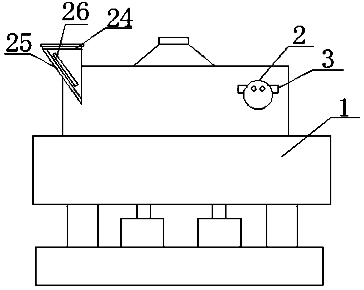
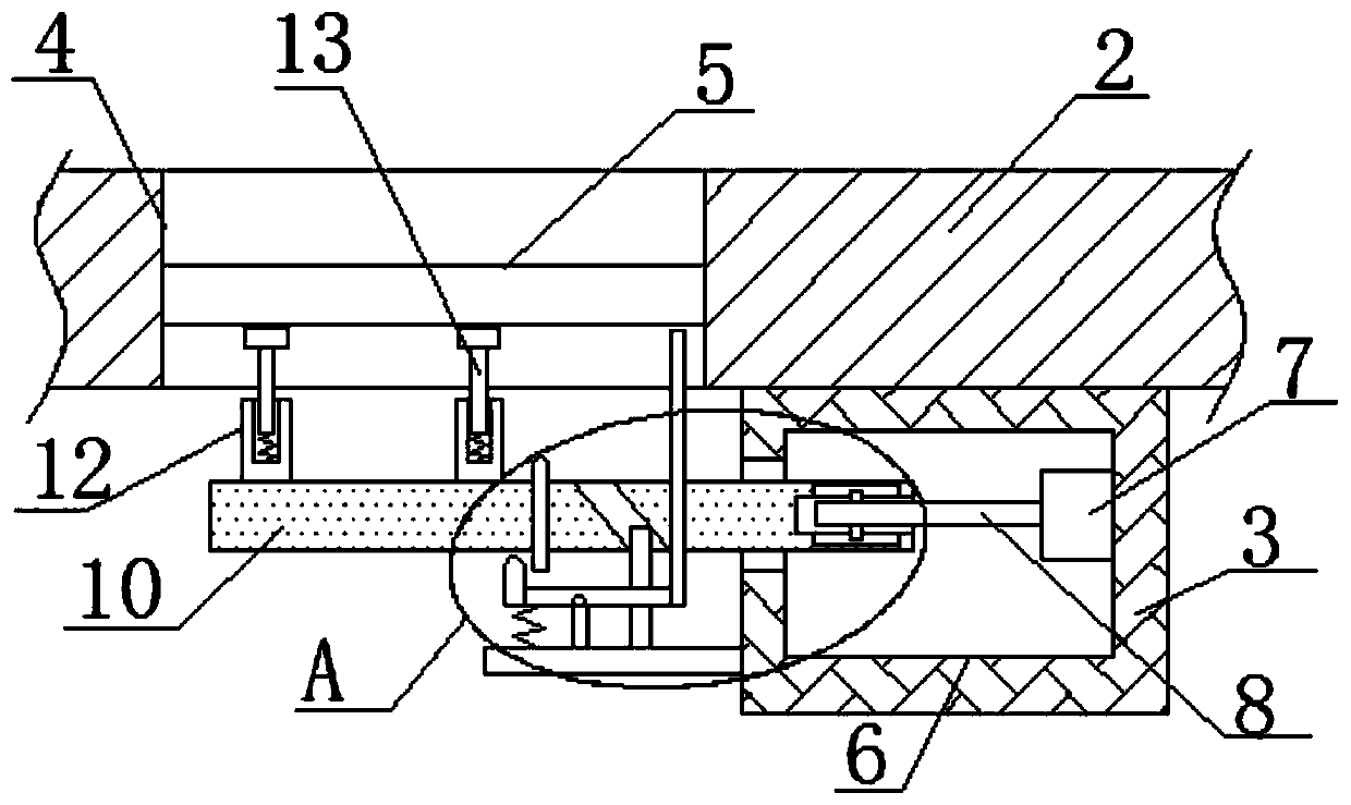
[0024] refer to Figure 1-5 , a water adding device for a double-disk cooler in a foundry, comprising a double-disc cooler 1, a respirator 2 is provided on the double-disc cooler 1, a support column 3 is provided on one side of the respirator 2, and a support column 3 is provided on one side of the respirator 2 There is a vent hole 4, a filter plate 5 is movably installed in the vent hole 4, a placement cavity 6 is opened on the support column 3, a motor 7 is fixedly installed on the inner wall of one side of the placement cavity 6, and the output shaft of the motor 7 is fixed by a coupling A rotating shaft 8 is installed, and a rotating ho...


PUM


Abstract

The invention discloses a casting factory double-disc cooler water adding device. The casting factory double-disc cooler water adding device comprises a double-disc cooler, a rebreather is arranged onthe double-disc cooler, a supporting column is arranged on one side of the rebreather, an air hole is formed in one side of the rebreather, and a filter plate is movably mounted in the air hole. A placing cavity is formed in the supporting column, a motor is fixedly mounted on the inner wall of one side of the placing cavity, a rotary shaft is fixedly mounted to an output shaft of the motor through a coupling, a rotary hole is formed in the inner wall of one side of the placing cavity, a rotary rod is movably mounted in the rotary hole, and two ends of the rotary rod extend out of the rotaryhole. The casting factory double-disc cooler water adding device has a reasonable structure, drives the rotary rod to rotate thought the operation of the motor, the rotary rod further can move duringcontinuous rotating, so that a hairbrush is driven to sufficiently wash the filter plate, meanwhile, vibration of a knocking rod enables blocking matter on the filter plate to be vibrated to fall, thefilter plate is conveniently and effectively cleaned, meanwhile, an anti-wearing plate is conveniently to be mounted on a buffer plate, and use is convenient.

Description

technical field [0001] The invention relates to the technical field of double-disc coolers, in particular to a water adding device for a double-disk cooler in a foundry. Background technique [0002] In the production of foundry enterprises, the increase of sand temperature has become a major factor that endangers the qualified rate of products, and the double-disc cooler has become a more commonly used equipment to reduce the sand temperature. [0003] Publication No. CN206356530U discloses a disc stirring cooler. The sand feeding device includes a sand inlet, a buffer plate, a wear-resistant plate and a windshield curtain, wherein the wear-resistant plate is installed on the upper surface of the buffer plate in the form of clamping. The top of the air curtain is installed on the inner side of the sand inlet. The mixing device includes a rotor and a mixing bucket. A respirator is installed on the side of the mixing bucket opposite to the sand feeding device. However, after ...

Claims


Application Information

Patent Timeline
IPC IPC(8): B22C5/08B01D46/10B01D46/00
CPCB22C5/08B01D46/10B01D46/76B01D46/681
Inventor 董家岩安通高争
Owner 济南市平阴县玛钢厂
Why Eureka
Try Eureka