
Charging control guiding method and system, power supply control device, and charging control device

A charging control and power supply control technology, which is applied to battery circuit devices, circuit devices, charging stations, etc., and can solve problems such as danger of electric shock to personnel, multiple connections of components, and complexity.

Inactive Publication Date: 2019-07-16
BORGWARD AUTOMOTIVE CHINA CO LTD
View PDF4 Cites 4 Cited by
  • Summary
  • Abstract
  • Description
  • Claims
  • Application Information

AI Technical Summary

Problems solved by technology

[0002] With the increasing popularity of electric vehicles, the charging system of electric vehicles has gradually attracted more and more people's attention. The problem that needs to be considered when conducting conductive charging for vehicles is: before using the charging interface for charging, it is necessary to confirm and test the charging Whether the interface has been reliably connected, and charging without complete connection may easily cause electric shock hazards; during the charging process, the power supply needs to output a PWM guide wave with a certain duty cycle through the charging interface to control the on-board charger. The duty cycle of the waveform can be adjusted in real time to adjust the charging current. At the same time, the output waveform and the connection status of the charging interface can be monitored in real time. Once an abnormal situation occurs, the power supply should be cut off immediately
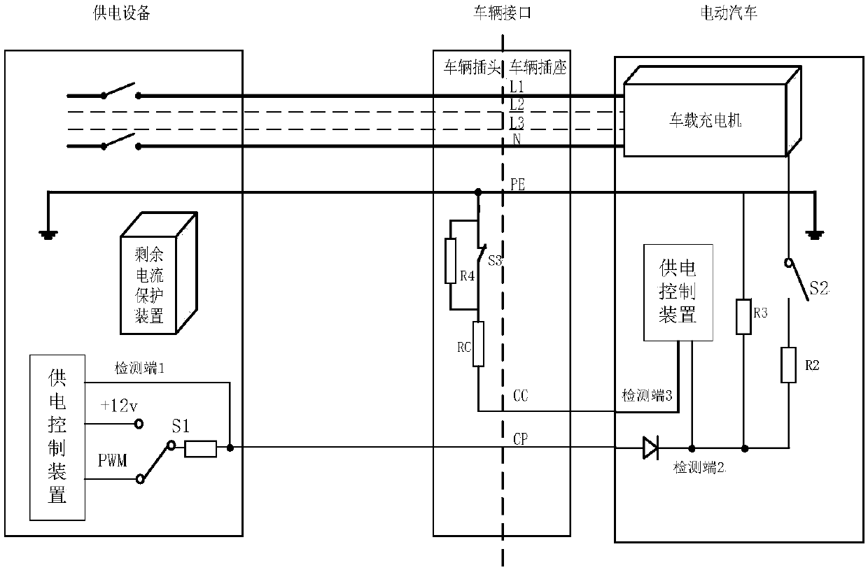
[0004] It can be seen from the above that when performing charging control guidance in the related art, it is necessary to switch the switch S1 in the power supply device and the switch S3 on the vehicle to complete the confirmation of the CP terminal. The circuit involves many components and the connection relationship is complicated.

Method used


Image

  • Charging control guiding method and system, power supply control device, and charging control device
  • Charging control guiding method and system, power supply control device, and charging control device
  • Charging control guiding method and system, power supply control device, and charging control device

Examples


Embodiment Construction

[0047] Specific embodiments of the present disclosure will be described in detail below in conjunction with the accompanying drawings. It should be understood that the specific embodiments described here are only used to illustrate and explain the present disclosure, and are not intended to limit the present disclosure.

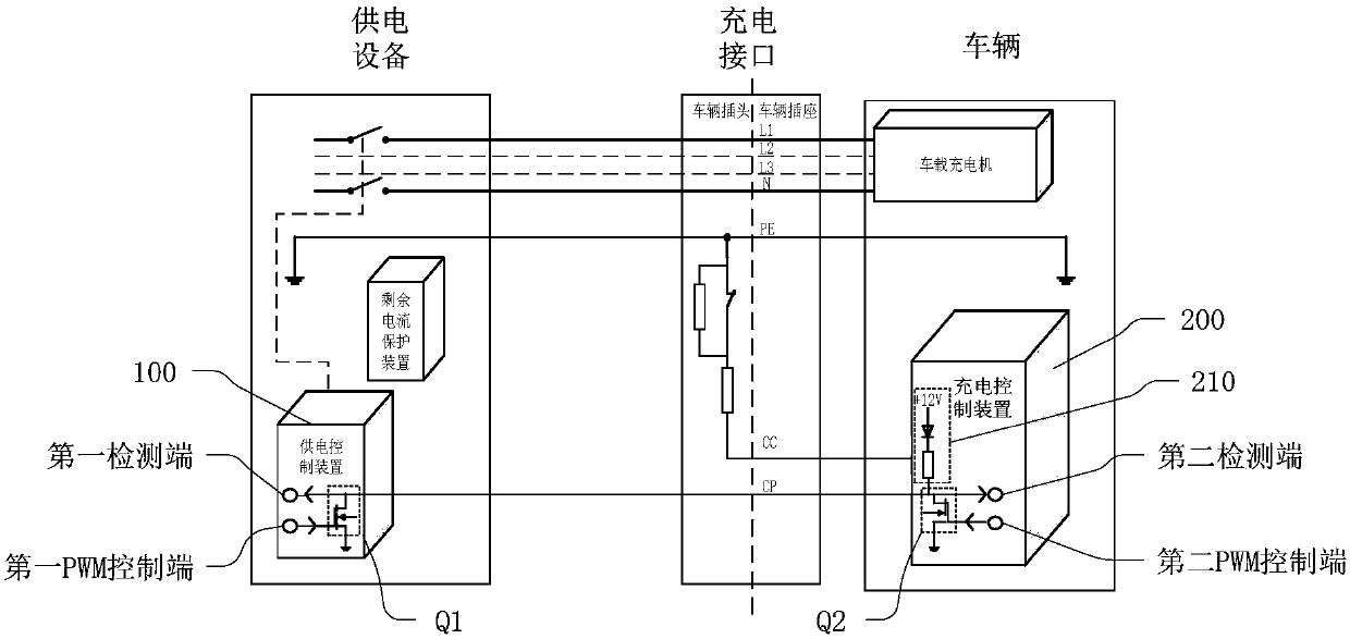
[0048] figure 2 is a schematic diagram of a charging control guidance system shown in an exemplary embodiment of the present disclosure, as shown in figure 2 As shown, the system includes a power supply control device 100 disposed on the power supply equipment;

[0049] The power supply control device 100 includes a first MOS transistor Q1, wherein the gate of the first MOS transistor Q1 is connected to the first PWM control terminal of the power supply control device 100, and the drain of the first MOS transistor Q1 is connected to The first detection terminal of the power supply control device 100, the source of the first MOS transistor Q1 is grounded; ...


PUM


Abstract

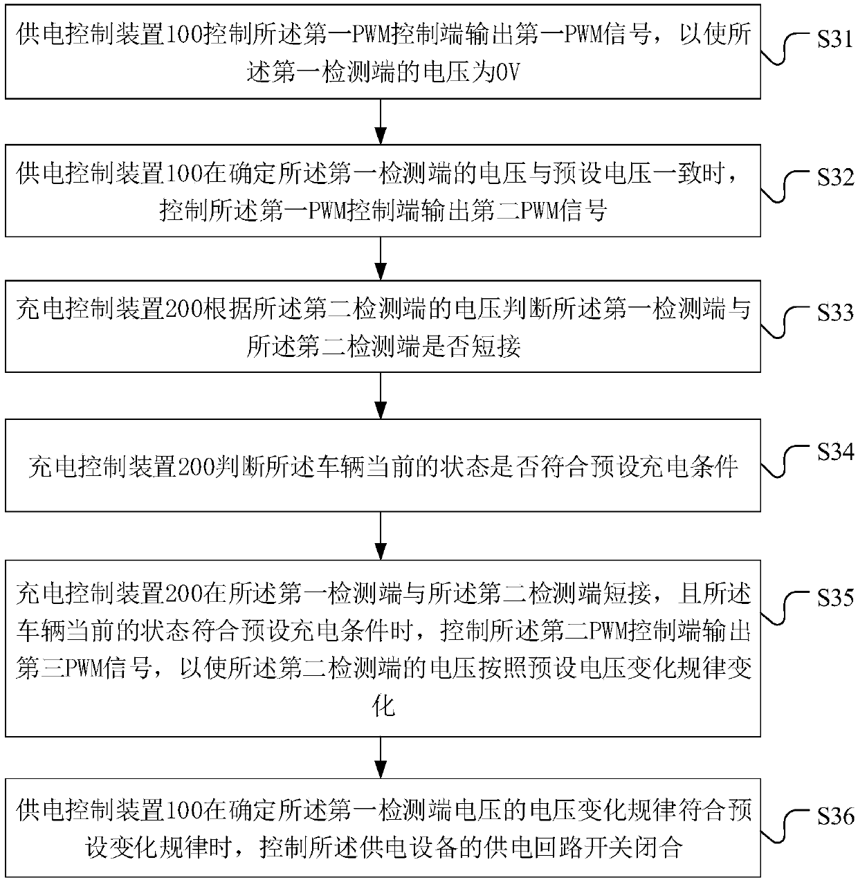
The invention provides a charging control guiding method and system, a power supply control device, and a charging control device to simplify a charging control guiding circuit in the related art. During a specific implementation, MOS tubesare connected withthe PWM control end and the detection end of the power supply control device (100) and the charging control device (200) correspondingly; thepower supply control device (100) determines the connection state of a vehicle and a charging device by sendinga first PWM signal and recovering the voltage ofa first detecting endand sends a second PWM signal when it is determined that the vehicle is connected with the charging device; the charging control device (200) on the vehicle determines the state of a power supply device by acquiring thesecond PWM signal sent by the power supply control device (100) and controls the voltage change of the second detecting end and the first detecting end by sending a third PWM signal to feed back the state of the charging control device, and thus confirmation of a charging control guiding CP is completed.

Description

technical field [0001] The present disclosure relates to the field of power transmission, and in particular, to a charging control guidance method and system, a power supply control device, and a charging control device. Background technique [0002] With the increasing popularity of electric vehicles, the charging system of electric vehicles has gradually attracted more and more people's attention. The problem that needs to be considered when conducting conductive charging for vehicles is: before using the charging interface for charging, it is necessary to confirm and test the charging Whether the interface has been reliably connected, and charging without complete connection may easily cause electric shock hazards; during the charging process, the power supply needs to output a PWM guide wave with a certain duty cycle through the charging interface to control the on-board charger. The duty cycle of the waveform can be adjusted in real time to adjust the charging current. ...

Claims


Application Information

Patent Timeline
IPC IPC(8): B60L53/14B60L53/66H02J7/00
CPCH02J7/0036B60L53/14B60L53/60Y02T90/16Y02T10/70Y02T90/14Y02T10/7072Y02T90/12
Inventor 王亚东
Owner BORGWARD AUTOMOTIVE CHINA CO LTD
Learn More