
Toner, image forming method and process cartridge

a technology of image forming and process cartridge, which is applied in the field of toner, can solve the problems of inability to achieve uniform or desired chargeability of toner, inevitably bulky apparatus for performing this mixing, and relatively difficult control of forming such a uniform layer

Inactive Publication Date: 2007-02-01
RICOH KK
View PDF14 Cites 96 Cited by
  • Summary
  • Abstract
  • Description
  • Claims
  • Application Information

AI Technical Summary

Benefits of technology

[0017] The present invention is to provide a toner by which quality images can be produced at high temperature and high humidity without image noise and without causing contamination in an image forming apparatus having a toner layer regulating member and its corresponding image forming method and process cartridge.

Problems solved by technology

Apparatus for performing this mixing is inevitably bulky, and therefore, the single component developing system is preferred in terms of reduction in size of an electrophotographic machine.
It is relatively difficult to control forming such a uniform layer in comparison with the case of the two-component developing system.
One of the reasons therefor is that a toner does not have a uniform or desired chargeability.
However, such a system using a magnetic sleeve uses a heavy permanent magnet.
As a result, a developing unit including such a system is inevitably large in size and complicated in structure.
In consideration of this, the system using a magnetic toner is not suitable to fully utilize merits of a single-component developing system.
Therefore, it is difficult to apply such a magnetic toner to a color printer.
However, for a developing system using such a developing device taking a non-magnetic and single-component developing system, which is “a developing device having a toner transfer member, a toner supplying member for supplying a toner to the surface of the toner transfer member, and a toner layer regulating member contacting the surface of the toner transfer member and regulating the layer thickness of the toner supplied to the surface of the transfer member”, it is not easy to improve the device in terms of quality images.
However, the effect of a complex of boron benzylic acid extremely deteriorates on environmental change, especially, at a high temperature and high humidity environment.

Method used


Image

  • Toner, image forming method and process cartridge
  • Toner, image forming method and process cartridge
  • Toner, image forming method and process cartridge

Examples


example 1

[0137] The following components are sufficiently mixed with a blender and then kneaded with a two-roll extruder.

Resin 174partsResin 326partsCharge controlling agent (Compound2.5partsrepresented by Chemical structure (1)Colorant (PigmentBlue 15:3)4parts

[0138] Subsequent to cooling down, the resultant is pulverized and classified to obtain a cyan color mother toner having a volume average particle diameter of 7.9 μm.

[0139] 100 parts of the mother toner and 0.4 parts of hydrophobic silica (surface treated with hexamethyl disilazane, the average particle diameter of the primary particle thereof: 0.02 μm) are mixed with a HENSCHEL MIXER to obtain a cyan color toner.

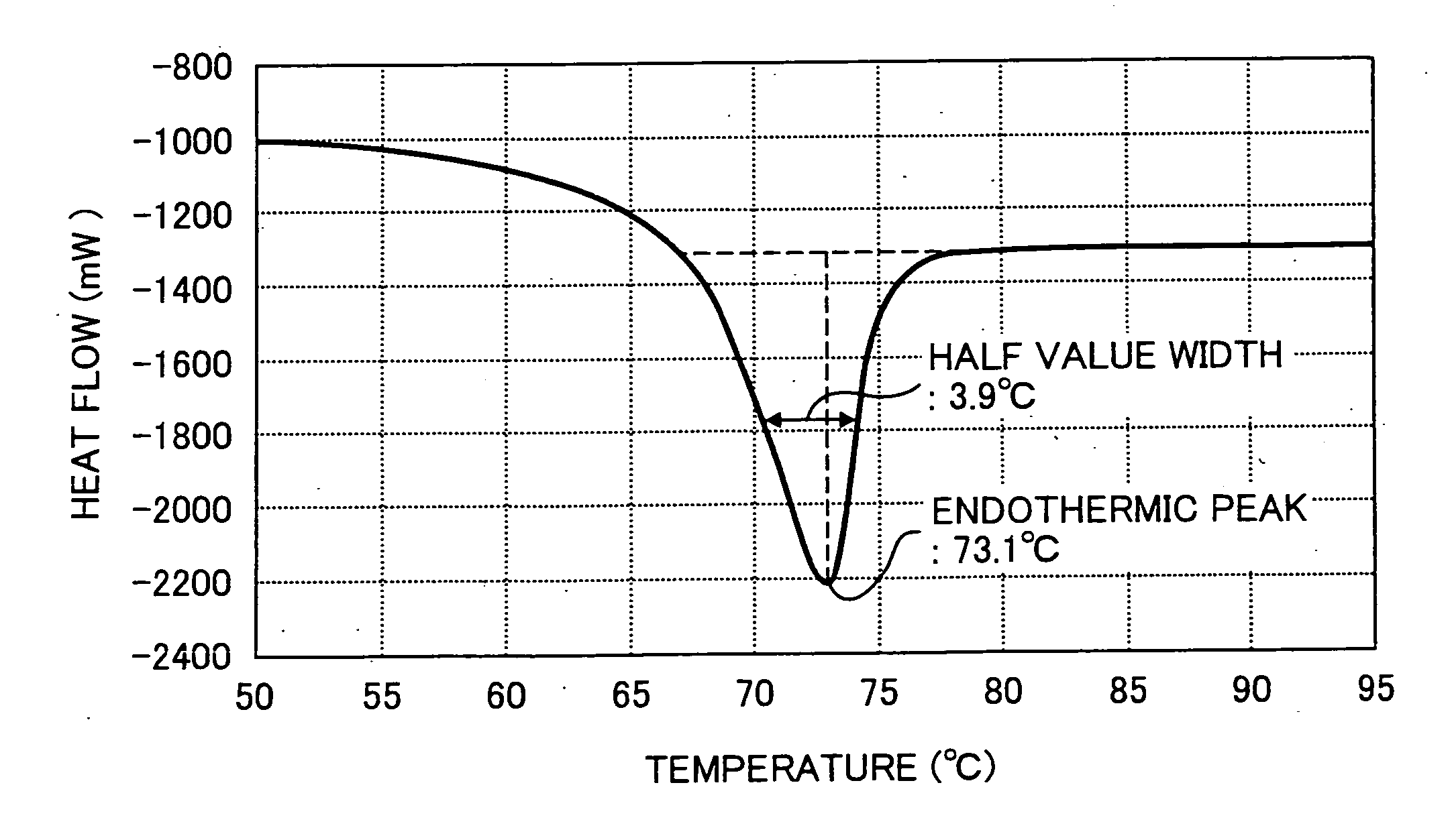
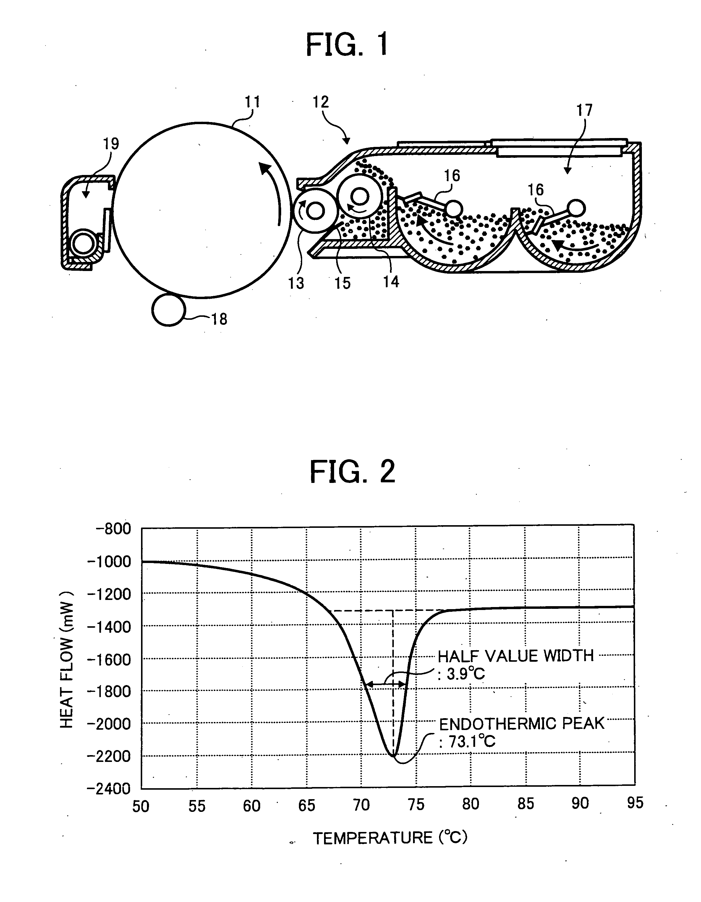
[0140] The endothermic curve of this toner (Toner 1) is measured by DSC6200 (manufactured by Seiko Instruments Inc.) based on differential scanning calorimetry according to the temperature rise and fall mentioned above. The DSC chart, and the endothermic peak and the half value width based thereon are shown in FIG. 2. In a...

examples 2 to 8

[0146] Toners 2 to 8 are manufactured and evaluated in the same manner as in Example 1 using the resin and wax components shown in Table 2.


PUM

PropertyMeasurementUnit
acid valueaaaaaaaaaa
surface roughnessaaaaaaaaaa
resistanceaaaaaaaaaa

Abstract

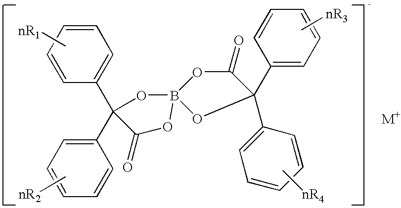
A toner containing a binder resin containing a resin having a polyester skeleton, a wax containing a hydrocarbon based wax, a colorant, and a charge controlling agent represented by the following chemical structure, wherein the toner has at least one endothermic peak in a range of from 60 to 80 ° C. when measured by a differential scanning calorimetry (DSC). In the chemical structure, M represents one of Li, Na and K, R1, R2, R3 and R4 each, independently, represent one of a hydrogen atom, an alkyl group having 1 to 4 carbon atoms, an alkoxy group having 1 to 4 carbon atoms, and a halogen atom, and n represents an integer of from 1 to 5, and when n is from 2 to 5, each of R1, R2, R3 and R4 can be different from the other.

Description

BACKGROUND OF THE INVENTION [0001] 1. Field of the Invention [0002] The present invention relates to a toner, and its corresponding image forming method and process cartridge. [0003] 2. Discussion of the Background [0004] In an image forming apparatus operating as electrophotographic system, toner images are formed through a charging process, an irradiating process, and a developing process. The charging process is a process of discharging the surface of a photoreceptor, i.e., an image bearing member or infusing charges thereto. The irradiating process is a process of irradiating the surface of the charged photoreceptor to form a latent electrostatic image thereon. The developing process is a process of developing the latent electrostatic image with a toner having a polarity reversed relative to the polarity of the latent electrostatic image formed on the surface of the photoreceptor. Subsequently, the toner image is transferred via a transfer process in which the toner image formed...

Claims


Application Information

Patent Timeline
Patent Type & Authority Applications(United States)
IPC IPC(8): G03G9/08
CPCG03G9/08755G03G9/08782G03G9/0975G03G9/08797G03G9/09741G03G9/08795
Inventor YAMAMOTO, ATSUSHIMIKURIYA, YOSHIHIROKUROSE, KATSUNORIHAGI, MASAYUKIKADOTA, TAKUYAKATOH, HIROAKIINOUE, MASAHIDE
Owner RICOH KK
Learn More