Alignment mechanism for automatic charging, charging equipment and charging system

An alignment mechanism and automatic charging technology, which is applied to electric vehicle charging technology, charging stations, electric vehicles, etc., can solve the problems of position deviation and low efficiency of AGV automatic charging, and achieve the effect of eliminating position deviation

Pending Publication Date: 2019-07-16
HANGZHOU HIKROBOT TECH CO LTD
View PDF6 Cites 8 Cited by
  • Summary
  • Abstract
  • Description
  • Claims
  • Application Information

AI Technical Summary

Problems solved by technology

However, due to control accuracy and other reasons, the connectors of the AGV and the connectors of the charging equipment will also have positional deviations in other directions, especially in the left and right directions.
When there is a positional deviation between the connector of the AGV and the connector of the charging device in other directions, it is necessary to repeatedly adjust the position of the AGV to make the AGV adapt to the position of the charging device to complete the docking of the connector of the AGV and the connector of the charging device. This makes AGV automatic charging less efficient

Method used


Image

  • Alignment mechanism for automatic charging, charging equipment and charging system
  • Alignment mechanism for automatic charging, charging equipment and charging system
  • Alignment mechanism for automatic charging, charging equipment and charging system

Examples


Embodiment 1

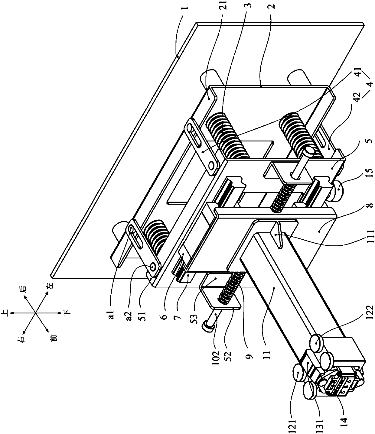
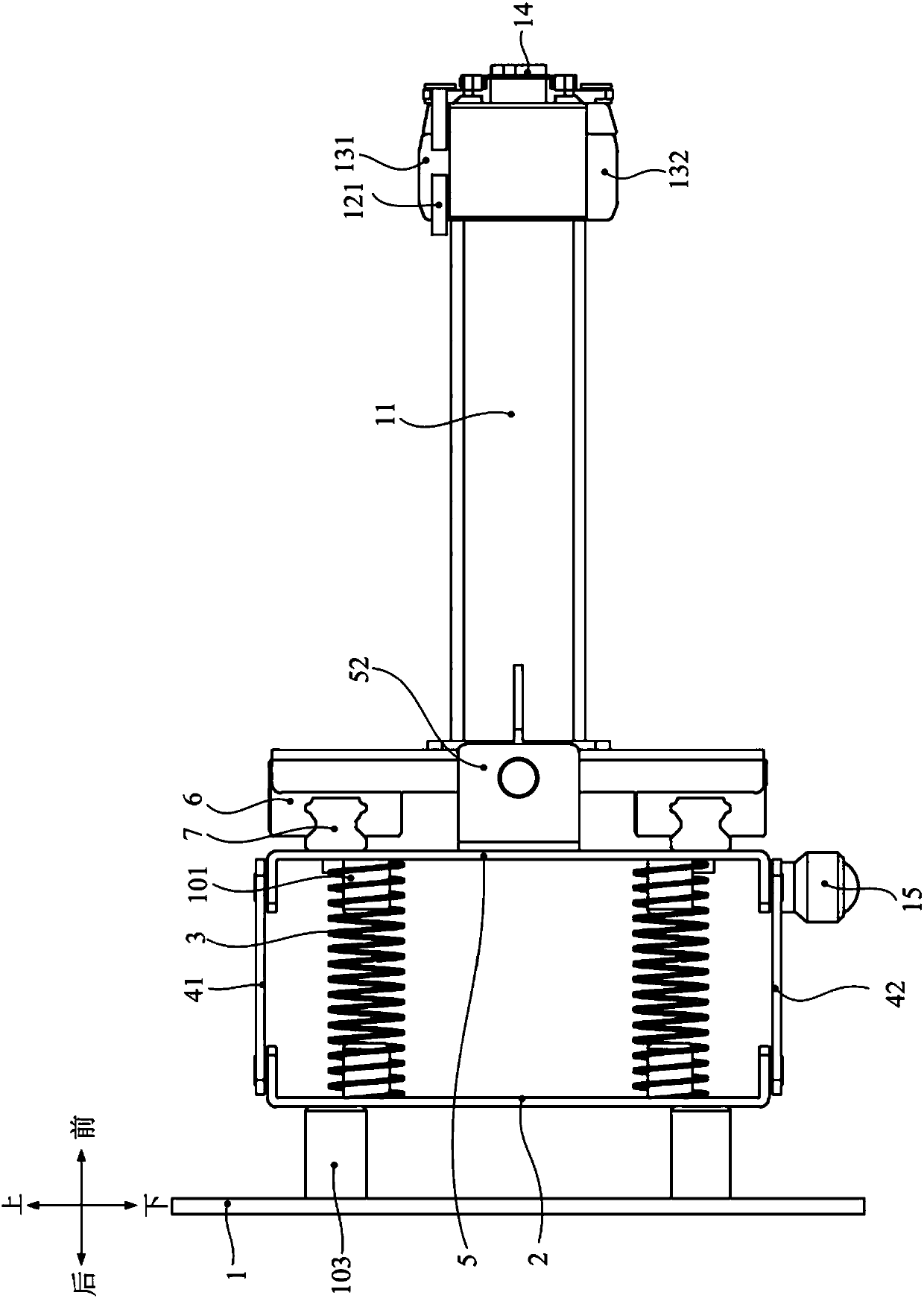
[0091] This embodiment provides an alignment mechanism for automatic charging, figure 1 A schematic diagram of the three-dimensional structure of the alignment mechanism provided in this embodiment, figure 2 A schematic diagram of the planar structure of the alignment mechanism provided in this embodiment, such as figure 1 with figure 2 As shown, the alignment mechanism consists of:

[0092] a first substrate 2 arranged vertically;

[0093] a second substrate 5 arranged opposite to the first substrate 2;

[0094] A first spring 3 whose two ends are respectively connected to the opposite surfaces of the first substrate 2 and the second substrate 5;

[0095] And, a limiting component arranged between the first base plate 2 and the second base plate 5 .

[0096] Wherein, the limiting assembly includes at least two limiting plates 4 that are parallel to each other and located in the same horizontal plane. The opposite surfaces of the first substrate 2 and the second substr...

Embodiment 2

[0151] This embodiment provides a charging device for automatic charging, and the charging device includes: an alignment mechanism and a first connector 14 connected to the alignment mechanism. Wherein, the alignment mechanism is the alignment mechanism provided in the first embodiment.

[0152] Due to the use of the alignment mechanism provided in Embodiment 1, applying the charging device provided in this embodiment to automatic charging of equipment such as AGVs can effectively improve automatic charging efficiency.

[0153] According to the description in Embodiment 1, when only the first movable unit including the first substrate 2, the second substrate 5, the first spring 3, the limit plate 4 and related components is provided in the alignment mechanism, the first connector 14 is directly fixed on the surface of the second substrate 5 away from the first substrate 2; when the alignment mechanism is provided with a second movable unit including a third substrate 8, a slid...

Embodiment 3

[0156] This embodiment provides a charging system for automatic charging, Figure 4 A schematic diagram of the three-dimensional structure of the charging system provided in this embodiment, Figure 5 A schematic plan view of the charging system provided in this embodiment, such as Figure 4 with Figure 5 As shown, the charging system includes an alignment mechanism arranged in the charging device, a first connector 14 connected to the alignment mechanism, and a second connector 17 arranged on the AGV and matched with the first connector 14 . Wherein, the alignment mechanism is the alignment mechanism provided in the first embodiment.

[0157] According to the description in Embodiment 1, when only the first movable unit including the first substrate 2, the second substrate 5, the first spring 3, the limit plate 4 and related components is provided in the alignment mechanism, the first connector 14 is directly fixed on the surface of the second substrate 5 away from the fi...


PUM


Abstract

The invention discloses an alignment mechanism for automatic charging, charging equipment and a charging system, and belongs to the technical field of automatic charging. The alignment mechanism includes a first base plate, a second base plate, a first spring and a limiting assembly, wherein the first base plate is arranged in the vertical direction, the second base plate is arranged opposite to the first base plate, the two ends of the first spring are separately connected to the opposite surfaces of the first base plate and the second base plate, and the limiting assembly is arranged betweenthe first base plate and the second base plate. The limiting assembly comprises at least two limiting plates parallel to each other and located in the same horizontal plane, and the two ends of eachlimiting plate are connected to the opposite surfaces of the first base plate and the second base plate in a manner which the limiting plates are enabled to rotate in the horizontal planes where the limiting plates are located separately. The alignment mechanism can automatically adapt to the position of an automated guided vehicle (AGV), the alignment mechanism is arranged in the charging equipment, a connector of the charging equipment is enabled to be connected with the surface, deviating from the first base plate, of the second base plate, so that when the AGV is automatically charged, theconnector of the charging equipment and a connector of the AGV can be quickly connected.

Description

technical field [0001] The invention relates to the technical field of automatic charging, in particular to an alignment mechanism, charging equipment and a charging system for automatic charging. Background technique [0002] Automated Guided Vehicle (AGV for short) is an unmanned vehicle equipped with automatic guidance devices such as electricity, magnetism or optics, which can drive along the prescribed guidance path, and has safety protection and various transfer functions. Drive a transporter. AGV uses a rechargeable battery as a power source, and uses automatic charging to charge the battery. When charging is required, the AGV approaches the charging device in a backward manner, so that the connector arranged at the tail of the AGV is docked with the connector of the charging device, thereby charging the AGV. The charging device is usually provided with an alignment mechanism to facilitate the docking of the connector of the AGV and the connector of the charging dev...

Claims


Application Information

Patent Timeline
Patent Type & Authority Applications(China)
IPC IPC(8): B60L53/35
CPCB60L53/36Y02T10/70Y02T10/7072Y02T90/12
Inventor 吕王彪刘昊
Owner HANGZHOU HIKROBOT TECH CO LTD
Why Eureka
Try Eureka