
Collimator and double-perspective imaging system

An imaging system and collimator technology, applied in the field of scanning imaging, can solve problems such as unfavorable modularization and refinement of the scanning system, occupying a large amount of space in the scanning system, increasing the difficulty of manufacturing, etc., achieving good imaging effects and simplifying the adjustment process , the effect of reducing the difficulty of manufacturing

Pending Publication Date: 2019-04-26
POWERSCAN COMPANY LIMITED
View PDF5 Cites 0 Cited by
  • Summary
  • Abstract
  • Description
  • Claims
  • Application Information

AI Technical Summary

Problems solved by technology

In the process of realizing the invention, the inventor found that the above-mentioned dual-view imaging scanning device has the following disadvantages in adjusting the scanning rays: first, because there is a certain angle between the two scanning rays, the two collimators are generally set at a distance from the radiation source. Farther away to avoid mutual interference, however, the two beams of scanning rays are fan-shaped, as the distance between the collimator and the radiation source increases, the projection of the scanning rays on the collimator becomes longer, and the length of the beam slit It also inevitably increases, resulting in a larger size of the collimator. The larger size of the collimator not only increases the difficulty of manufacturing, but also occupies a lot of space in the scanning system where the collimator is located, which is not conducive to the module of the scanning system. Second, when it is necessary to adjust the angle and position of the scanning ray, the two collimators need to be adjusted several times to make the scanning ray accurately enter the sensitive area of ​​the detector, and the adjustment process is complicated

Method used


Image

  • Collimator and double-perspective imaging system
  • Collimator and double-perspective imaging system
  • Collimator and double-perspective imaging system

Examples


specific Embodiment approach

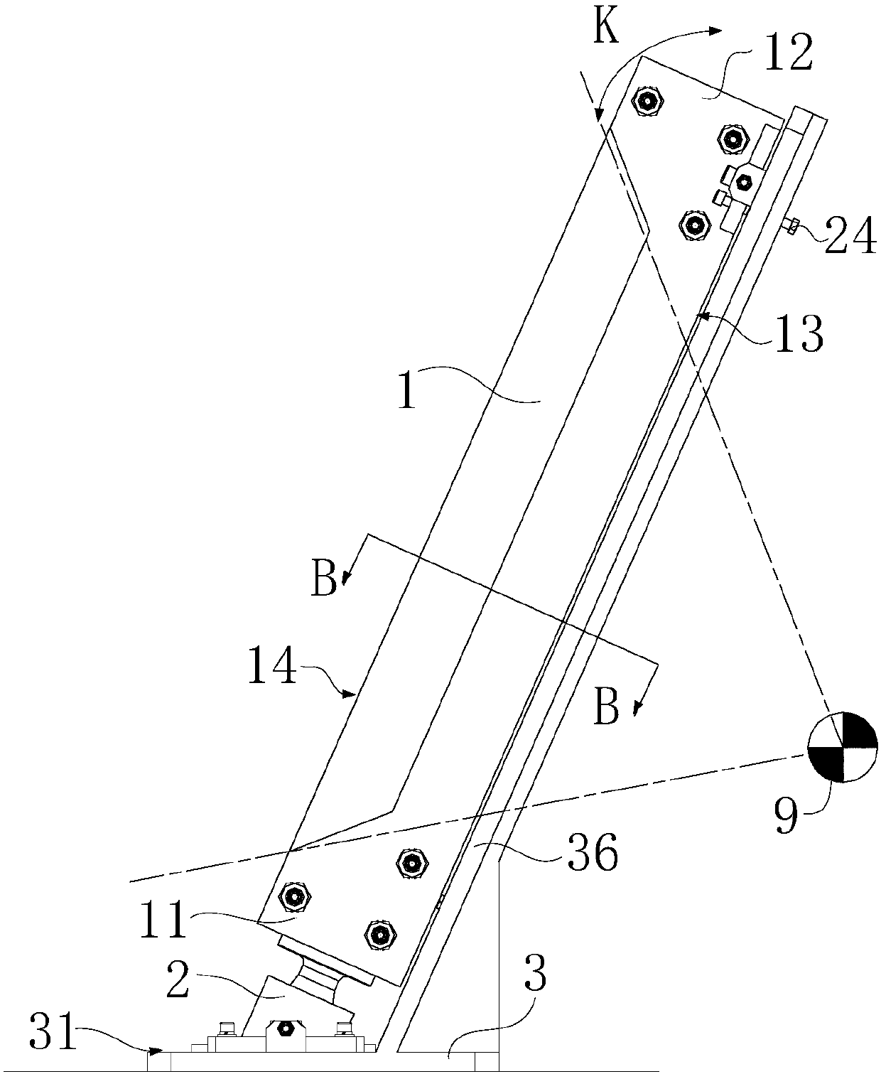
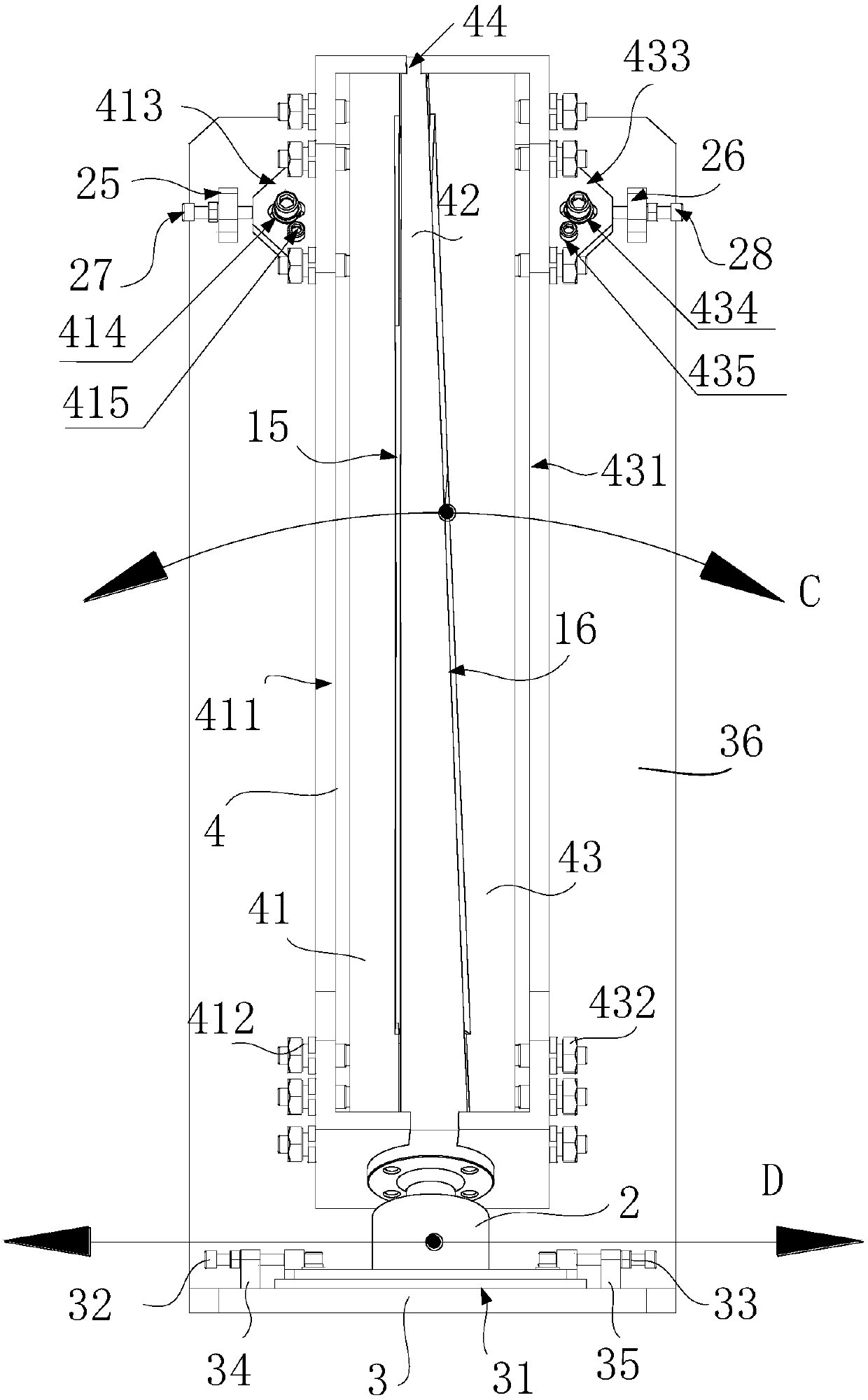
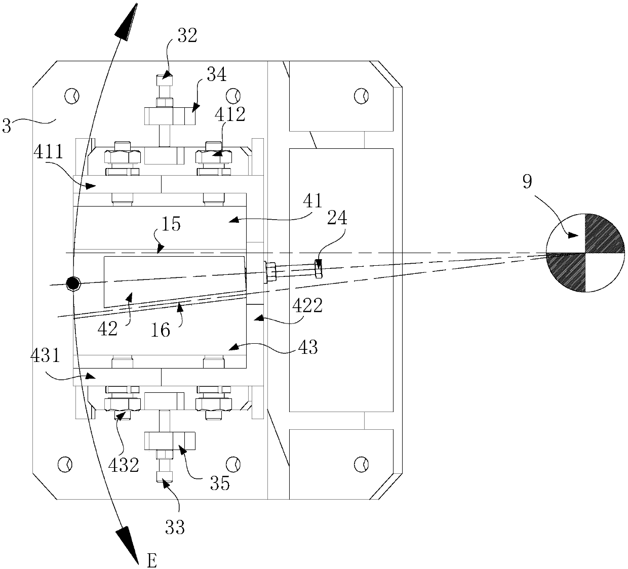
[0042] Such as figure 2 As shown, this embodiment provides a specific implementation method for adjusting the sliding of the mounting base 2 on the mounting surface 31: the collimator also includes a first adjusting stud 32 and a second adjusting stud 33, and the mounting surface 31 is installed with respectively The first adjustment plate 34 and the second adjustment plate 35 are located on both sides of the mounting base 2 .

[0043] The first adjustment stud 32, the second adjustment stud 33, the first adjustment plate 34, and the second adjustment plate 35 form a first adjuster, the first adjustment plate 34 is provided with a first threaded hole, and the second adjustment plate 35 There is a second threaded hole on the top, and the first adjusting stud 32 abuts on the mounting seat 2 after passing through the first threaded hole; the second adjusting stud 33 abuts on the mounting seat 2 after passing through the second threaded hole. 2 on. The first adjusting stud 32 a...


PUM


Abstract

The invention discloses a collimator and a double-perspective imaging system. The collimator comprises a slidable installation seat and an adjusting part, the adjusting part comprises an incident surface and an emergent surface which are arranged oppositely, a first beam seam and a second beam seam are formed in the adjusting part, the installation seat is slidably arranged, and the adjusting partis rotatably installed on the installation seat. The two-perspective imaging system comprises a radiation source, the collimator and a detection assembly, and the detection assembly comprises a firstdetector group and a second detector group; the first detector group comprises a plurality of detectors, and the second detector group comprises a plurality of detectors; the first detector group isarranged facing an outlet of the first beam seam; and the second detector group is arranged facing an outlet of the second beam seam. According to the collimator and the double-perspective imaging system, the size of the collimator is decreased, the manufacturing difficulty of the collimator is lowered, the space of a scanning system taken up by the collimator is reduced, modularization and refinement of the scanning system are promoted, and the adjusting process is simplified.

Description

technical field [0001] The invention relates to the technical field of scanning imaging, in particular to a collimator and a dual-view imaging system. Background technique [0002] Multiple objects arranged along the emission direction of the scanning rays cannot be accurately resolved in the single-view scanning technology. The dual-view imaging scanning technology uses two scanning rays at a certain angle to scan and detect objects in multiple directions, realizing multi-directional scanning. Object overlapping imaging resolution technology. [0003] In the prior art, the dual-view imaging scanning technology generally sets two collimators between the radiation source and the detector, and the two collimators are respectively installed on two collimator columns, and each collimator has a There is a beam slit, and the to-be-collimated scanning rays emitted by the radiation source pass through the collimator after being adjusted by two beam slits, scan the object to be dete...

Claims


Application Information

Patent Timeline
Patent Type & Authority Applications(China)
IPC IPC(8): G21K1/02
CPCG21K1/02
Inventor 郭近贤曹艳锋刘铮王彦华王春雷冯志涛
Owner POWERSCAN COMPANY LIMITED
Learn More