A friction stir extrusion method and device based on a stirring needle

A friction stirring and extrusion device technology, applied in ceramic extrusion dies, manufacturing tools, ceramic molding machines, etc., can solve problems such as component segregation, reinforcement phase and matrix metal separation and grain growth, etc., to achieve stable structure and performance Effect

Active Publication Date: 2021-05-25
NANCHANG HANGKONG UNIVERSITY
View PDF5 Cites 0 Cited by
  • Summary
  • Abstract
  • Description
  • Claims
  • Application Information

AI Technical Summary

Problems solved by technology

The disadvantage of this method is that it is easy to cause the separation of the reinforcement phase and the matrix metal, as well as the grain growth and composition segregation during the cooling process of the material.

Method used


Image

  • A friction stir extrusion method and device based on a stirring needle
  • A friction stir extrusion method and device based on a stirring needle
  • A friction stir extrusion method and device based on a stirring needle

Examples


Embodiment 1

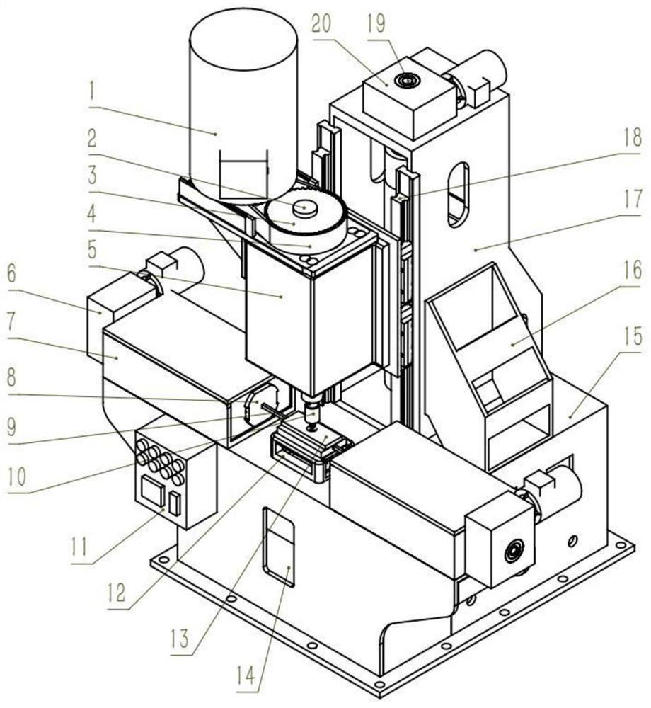
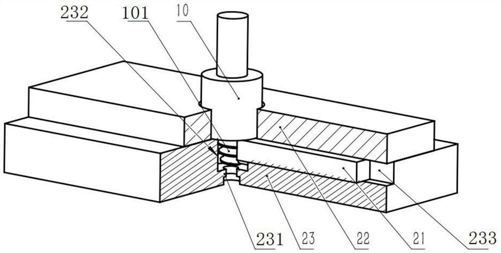
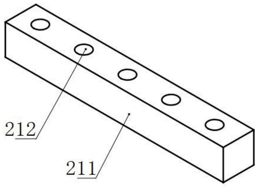
[0043] like figure 1As shown, the friction stir extrusion device based on the stirring needle 101 in this embodiment includes a base 15, and the base 15 is provided with a mold 23 assembly 13, an extrusion assembly and a lifting assembly. The mold 23 assembly 13 includes a mold 23 and is provided on the mold 23. The cover plate 22, the mold 23 and the anvil 12 are connected by fasteners, the anvil 12 and the base 15 are connected by fasteners, a feed slot is provided between the die 23 and the cover plate 22, and a prefabricated feed slot is arranged in the feed slot. The body 21, the cover plate 22 is provided with a through hole communicating with the mold stirring area 232, the feed slot is communicated with the mold stirring area 232, the base 15 is provided with a cavity corresponding to the mold outlet 231 at the bottom of the mold 23, and the side wall of the cavity is provided with a cavity. There is a viewing window 14; the extrusion assembly includes a box body 7, a ...

Embodiment 2

[0051] like Figure 5 As shown, this embodiment provides a friction stir extrusion device based on the stirring needle 101. On the basis of the first embodiment, the friction stir extrusion device based on the stirring needle 101 in this embodiment also has the following characteristics: the mold 23 is a The polygonal mold 2423 is provided with multiple groups of feeding troughs on the polygonal mold 2423 . Each set includes two slots. Multiple sets of different materials can be mixed simultaneously during extrusion. In the specific operation process, the material in the groove of the mold 23 can be stirred, mixed and extruded in stages according to the required properties of the material. For example, materials with different functions are placed in the first feeding slot 241, the second feeding slot 242, and the third feeding slot 243, respectively, and materials with different functions can be obtained according to different feeding sequences. For example, one kind of fu...

Embodiment 3

[0053] like Figure 6-10 As shown, this embodiment provides a friction stir extrusion device based on the stirring needle 101. On the basis of the first embodiment, the friction stir extrusion device based on the stirring needle 101 in this embodiment also has the following characteristics: the mold 23 adopts The split-type mold 26 is used so that the size of the stirring holes in the stirring area 232 of the mold can meet the requirements; The split mold 26 is in transition fit with the bracket 17 of the mold 23 , and the feed chute of the split mold 26 is slightly larger than the feed chute of the bracket 17 of the mold 23 . Figure 7 It is an axial cross-sectional three-dimensional structural schematic diagram of the split mold 26 in the present invention. like Figure 8-10 As shown, the shape of the split die outlet 261 is circular, and can also be a square or a pattern.


PUM


Abstract

The invention discloses a friction stirring extrusion device based on a stirring needle. A mold assembly, an extrusion assembly and a lifting assembly are arranged on the base, the mold assembly includes a mold and a cover plate, and a feeding groove is arranged between the mold and the cover plate. A prefabricated body is arranged in the trough, the feed trough communicates with the mold stirring area, and the base is provided with a cavity corresponding to the mold outlet at the bottom of the mold; the extrusion assembly includes a box body, a horizontal first screw rod arranged in the box body, The moving slider and the first driving device are provided with an extruding rod facing the feeding chute; the lifting assembly includes a bracket, a second screw rod, a slider and a second driving device, and the slider is fixedly connected with a main shaft The main shaft box is provided with a third driving device capable of driving the main shaft to rotate. The bottom end of the main shaft is connected with a stirring head facing the mold stirring area, and a stirring needle is arranged on the stirring head. The stirring and friction extrusion method and device based on the stirring pins of the present invention realize sufficient stirring, mixing and extrusion of composite materials.

Description

technical field [0001] The invention relates to the technical field of material forming, in particular to a stirring pin-based friction stirring extrusion method and device. Background technique [0002] The rapid development of science and technology has put forward higher and higher requirements on the performance of materials. Traditional materials already have certain limitations, such as low elastic modulus of aluminum alloy, large thermal expansion coefficient, and low thermal conductivity of titanium alloy. Metal matrix composites have become the research focus of many enterprises and research institutes because of their high specific strength, specific stiffness and high temperature performance. [0003] The preparation process is a key factor affecting the performance and application of composite materials. In the previous preparation methods, such as stirring casting method, the matrix metal is first melted, and then a reinforcing phase such as CNTs, SiC particles...

Claims


Application Information

Patent Timeline
Patent Type & Authority Patents(China)
IPC IPC(8): B22F3/20B22F1/00B29C48/30B29C48/36B29C48/86B29C48/87B28B3/20B28B3/26
CPCB22F1/0003B22F3/20B28B3/20B28B3/26B28B3/2654B29C48/30B29C48/36B29C48/865B29C48/87
Inventor 刘强柯黎明胡锦扬刘奋成
Owner NANCHANG HANGKONG UNIVERSITY
Why Eureka
Try Eureka