Low-noise pneumatic tire assembly

A pneumatic tire and low-noise technology, which is applied in the field of low-noise pneumatic tire components, can solve the problems of increasing tire weight, difficulty in repair fluid flow, and high cost, so as to improve the sound absorption and noise reduction effect, increase the effective sound absorption area, and reduce the material cost effect

Inactive Publication Date: 2019-07-19
GITI RADIAL TIRE (ANHUI) CO LTD +1
View PDF7 Cites 0 Cited by
  • Summary
  • Abstract
  • Description
  • Claims
  • Application Information

AI Technical Summary

Problems solved by technology

[0003] 1. The sound-absorbing material layer is laid to make use of the sound-absorbing effect of the sound-absorbing material, and does not significantly change the shape and size of the tire cavity. In order to obtain a better noise reduction effect, it is necessary to lay the sound-absorbing material along the entire circumference of the tire The layer does not need to reach a certain thickness and width, but the related form increases the weight of the tire, and the amount of sound-absorbing material is large and the cost is high;
[0004] 2. Since the sound mode shape of the tire cavity between 150 and 250 Hz is distributed along the tire circumference, the sound-absorbing material layer laid along the entire circumference of the tire is usually parallel to the sound mode shape, and there is only a single The pore surface faces the tire cavity, so the sound absorption performance of the sound-absorbing material cannot be fully exerted, which greatly reduces the sound-absorbing effect;
[0005] 3. Since it needs to be laid continuously along the entire circumference of the tire and reach a certain thickness and width requirements, it is difficult to avoid damage to the sound-absorbing material layer during the installation and removal of the tire
[0006] 4. Since the sound-absorbing material layer needs to be laid continuously along the entire circumference of the tire, covering most of the inner surface of the tire tread, it brings difficulties to the flow of the repair fluid along the inner surface of the tire tread, making the pneumatic tire Puncture repairs are difficult to perform quickly and reliably

Method used


Image

  • Low-noise pneumatic tire assembly
  • Low-noise pneumatic tire assembly
  • Low-noise pneumatic tire assembly

Examples


Embodiment Construction

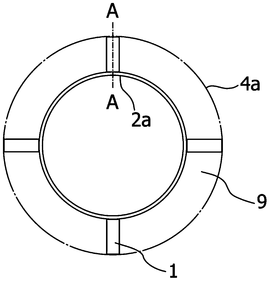
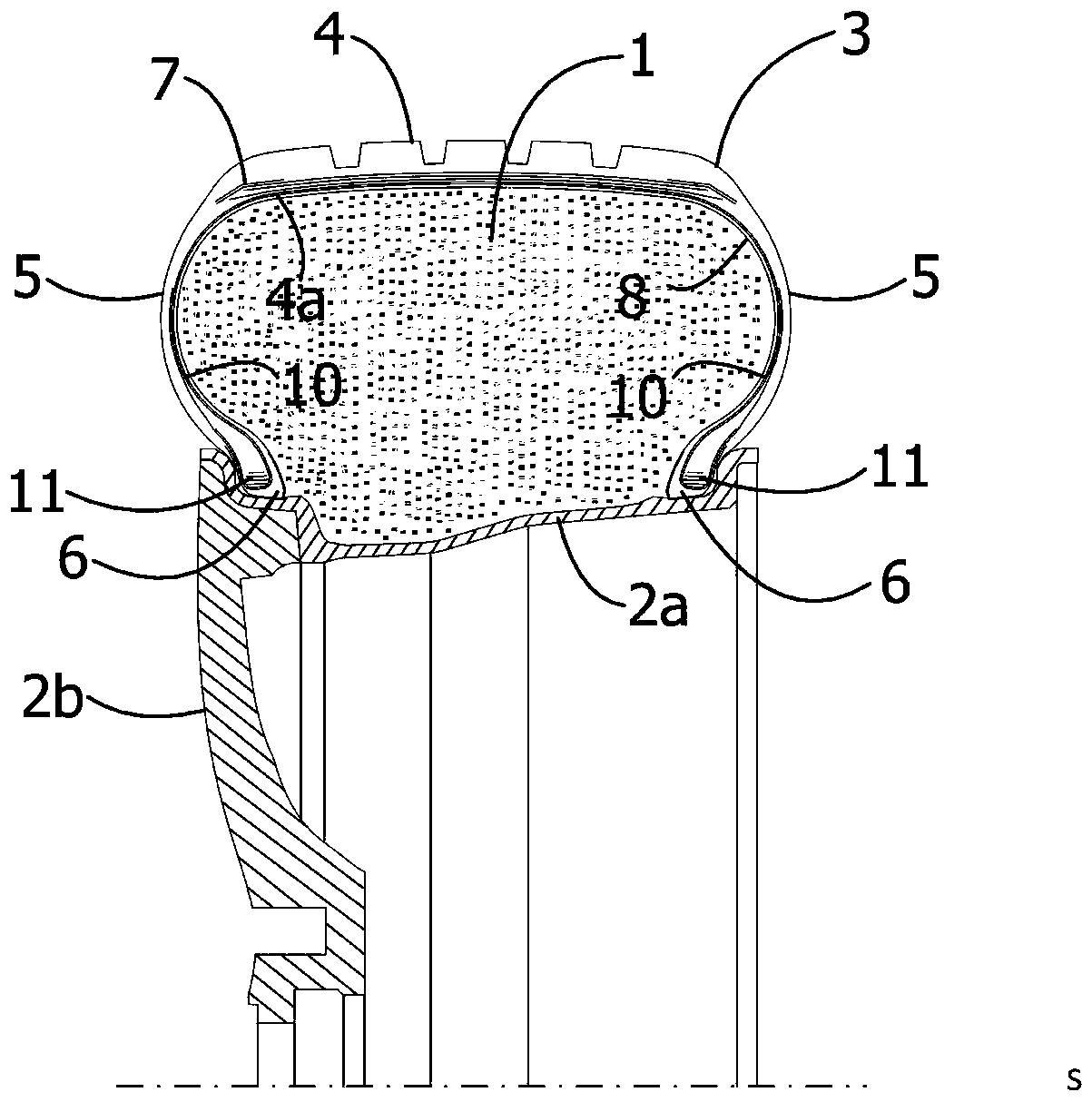
[0032] see figure 1 and figure 2 , the pneumatic tire assembly in this embodiment refers to the pneumatic tire 3 formed with the annular tire cavity 9 by the tread inner surface 4a of the tire and the rim 2a; the pneumatic tire 3 is installed on the rim 2a and supported by the spokes 2b; The tire 3 includes: a tread portion 4, a bead portion 6 on the left and right sides, sidewall portions 5 on the left and right sides connecting the tread portion 4 and the bead portion 6; A carcass 10 extends inside the tire, a belt 7 is provided on the outer peripheral side of the carcass of the tread portion 4, and bead cores 11 are embedded in the left and right bead portions 6, respectively, so that both ends of the carcass 10 are placed on the tire. The ring core 11 is turned back from the inner side of the tire to the outer side; the space surrounded by the tire inner surface 8 forms the cavity of the pneumatic tire 3, and the pneumatic tire 3 is installed on the wheel by sealing the ...


PUM


Abstract

The invention discloses a low-noise pneumatic tire assembly. An annular tire cavity is formed by the inner surface of a tread of a tire and a rim jointly. The low-noise pneumatic tire assembly is characterized in that energy dissipaters in a partition mode are arranged on the cross section of the annular tire cavity, the annular tire cavity is circumferentially divided into multiple sections through the energy dissipaters, the energy dissipaters are made of a porous sound absorption material, front and rear porous faces of the sound absorption material are arranged in the annular tire cavity,and the tire cavity resonance acoustic mode separation energy dissipaters are formed. The low-noise pneumatic tire assembly has the remarkable noise reduction performance and is light, economical anddurable.

Description

technical field [0001] The present invention relates to pneumatic tires, and more particularly to a low noise pneumatic tire assembly. Background technique [0002] Noise is an important indicator of the driving comfort of a passenger car. When the car is running, the cavity resonance sound generated by the cavity formed between the pneumatic tire and the rim is one of the important sources of car noise. The peak frequency of the cavity resonance sound is related to the size of the tire cavity. Generally, there is an obvious and sharp resonance peak between 150 and 250 Hz, which brings unpleasant feelings to the passengers in the car. In order to reduce the resonance noise of the tire cavity, there is a technical solution for continuously laying a layer of sound-absorbing material on the inner surface of the tire tread, but the related technical solutions have the following problems: [0003] 1. The sound-absorbing material layer is laid to make use of the sound-absorbing e...

Claims


Application Information

Patent Timeline
Patent Type & Authority Applications(China)
IPC IPC(8): B60C19/00
CPCB60C19/002
Inventor 郑英杰李宁学毕传兴郑昌军
Owner GITI RADIAL TIRE (ANHUI) CO LTD
Why Eureka
Try Eureka