Pedal feel simulator for vehicle and vehicle having same

A simulator and pedal technology, applied in the field of vehicles, can solve the problems of slow response speed of the braking system, inconvenient drivers, poor braking performance, etc., and achieve convenient production, transportation, installation and use, fast braking response, and reasonable braking force. Effect

Active Publication Date: 2021-09-03
BYD CO LTD
View PDF9 Cites 0 Cited by
  • Summary
  • Abstract
  • Description
  • Claims
  • Application Information

AI Technical Summary

Problems solved by technology

However, the response speed of the brake system using hydraulic transmission mechanism or pneumatic transmission mechanism is slow and the braking performance is poor, which brings great inconvenience to the actual operation of the driver.

Method used


Image

  • Pedal feel simulator for vehicle and vehicle having same
  • Pedal feel simulator for vehicle and vehicle having same
  • Pedal feel simulator for vehicle and vehicle having same

Examples


Embodiment 1

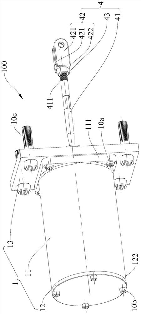
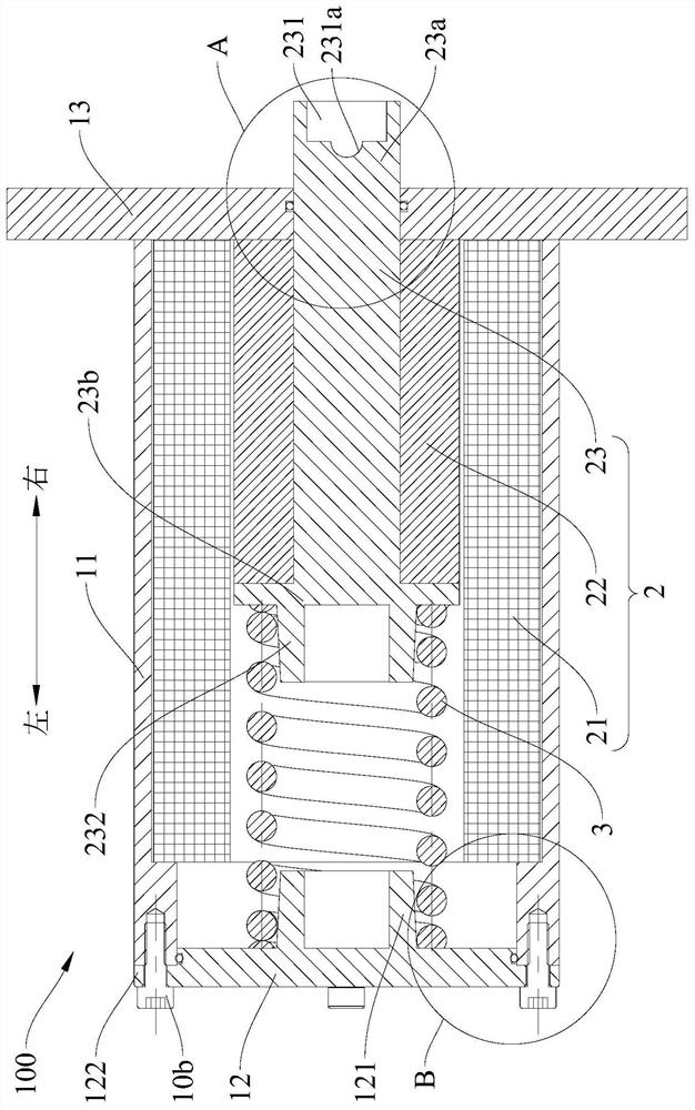
[0086] In this example, if Figure 1-Figure 7 As shown, the pedal feel simulator 100 includes a housing 1 , a linear motor 2 , an elastic member 3 and a connecting rod assembly 4 .

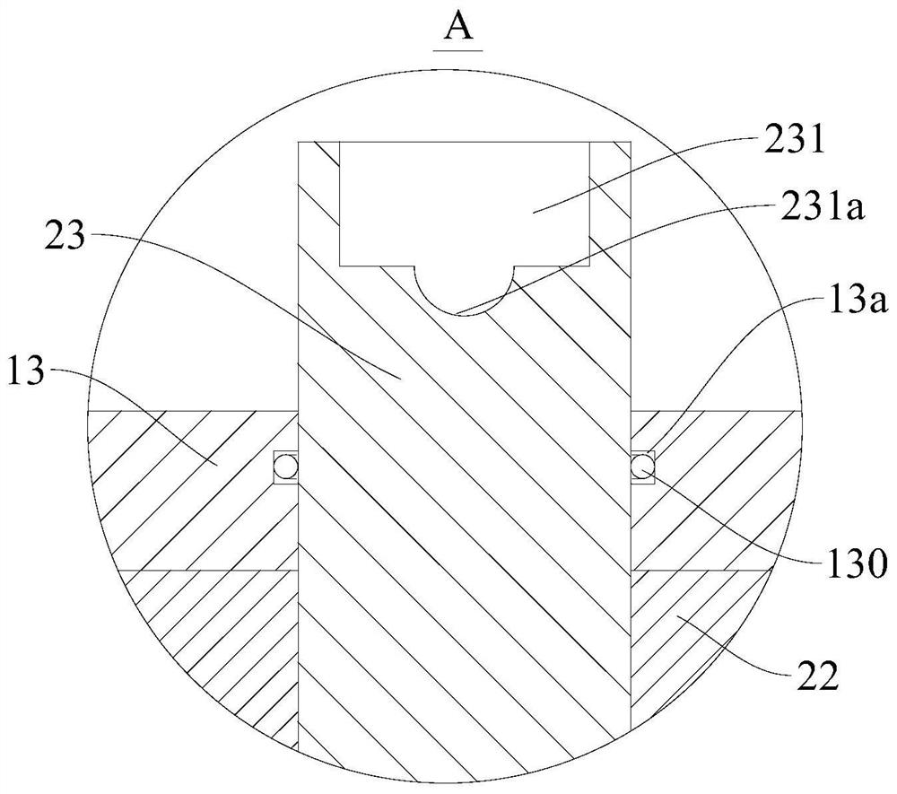
[0087]The housing 1 includes a main cylinder body 11, a bottom cover 12 and a fixed plate 13. The main cylinder body 11 is roughly formed into a cylindrical structure, the axial ends of the main cylinder body 11 are open, and the bottom cover 12 is arranged on the axial direction at one end (for example, if figure 2 The left end in), the fixed plate 13 is arranged on the axial other end of the main cylinder body 11 (for example, as figure 2 The right end of the middle), so that the bottom cover 12, the main cylinder body 11 and the fixed plate 13 jointly define an airtight accommodation space. Specifically, such as figure 1 and figure 2 As shown, a first connecting portion 111 is formed on the upper end of the main cylinder body 11, and the first connecting portion 111 protrudes outward alo...

Embodiment 2

[0095] like Figure 8 As shown, the structure of this embodiment is substantially the same as that of Embodiment 1, wherein the same components use the same reference numerals, the difference is that there are two elastic members 3; The brackets 10 are pivotably connected; the pedal 101 is provided with a stop member 101b that stops against the first end 23a of the motor push rod.

[0096] like Figure 8 As shown, the bottom cover 12 is provided with a first installation protrusion 121, the first installation protrusion 121 is formed by protruding upward from part of the inner wall of the bottom cover 12, and the upper end surface of the first installation protrusion 121 is provided with a third installation protrusion 123, the third installation protrusion 123 is formed by the part of the upper end surface of the first installation protrusion 121 protruding upwards, the first installation protrusion 121 and the third installation protrusion 123 are coaxially arranged, the fi...

Embodiment 3

[0103] like Figure 9 As shown, the structure of this embodiment is substantially the same as that of Embodiment 2, wherein the same components use the same reference numerals, the difference is that: the two elastic members 3 are respectively located on the axial sides of the motor primary 21; the second installation The protrusion 232 is fixedly mounted on the second end 23b of the motor push rod through a mounting screw 232b.

[0104] The two elastic pieces 3 are respectively a first elastic piece 31 and a second elastic piece 32, the first elastic piece 31 is located in the accommodation space, and the upper end of the first elastic piece 31 is sleeved on the outer peripheral wall of the second mounting protrusion 232, The lower end of the first elastic member 31 is sleeved on the outer peripheral wall of the first installation protrusion 121 . The second elastic member 32 is located in the accommodation space, and a stop portion 233 is formed on the motor push rod 23, so...


PUM


Abstract

The invention discloses a pedal feel simulator for a vehicle and a vehicle having the same. The vehicle includes a pedal, and the pedal feel simulator includes: a casing; a linear motor, the linear motor includes a motor primary, a motor secondary, and a motor push rod, and the motor The primary is fixed on the inner wall of the housing, and the secondary of the motor is set in the primary of the motor. The secondary of the motor cooperates with the primary of the motor so that the secondary of the motor can move axially relative to the primary of the motor. The secondary of the motor is sleeved on the push rod of the motor to drive the motor to push The rods move synchronously, and the first end of the motor push rod protrudes out of the casing to be suitable for being connected with the pedal; an elastic member for applying elastic force to the motor push rod. According to the pedal feeling simulator for vehicles of the present invention, the response speed is fast, the braking effect is good, and at the same time, the driver can be provided with good "braking feeling", especially pedal braking feeling.

Description

technical field [0001] The invention relates to the technical field of vehicles, in particular to a pedal feeling simulator for a vehicle and a vehicle with the same. Background technique [0002] In the related art, the pedals in the vehicle mainly use a hydraulic transmission mechanism or a pneumatic transmission mechanism for power transmission, so as to realize braking of the vehicle. However, the response speed of the brake system adopting the hydraulic transmission mechanism or the pneumatic transmission mechanism is relatively slow, and the braking performance is poor, which brings great inconvenience to the actual operation of the driver. Contents of the invention [0003] The present invention aims to solve at least one of the technical problems existing in the prior art. For this reason, the present invention proposes a kind of pedal feel simulator that is used for vehicle, and described pedal feel simulator has fast response speed, has good braking effect, can ...

Claims


Application Information

Patent Timeline
Patent Type & Authority Patents(China)
IPC IPC(8): B60T8/40B60T7/06
CPCB60T7/06B60T8/409
Inventor 滕俊辉莫永才王铁君李传博刘苏丽
Owner BYD CO LTD
Why Eureka
Try Eureka