Eureka AIR delivers breakthrough ideas for toughest innovation challenges, trusted by R&D personnel around the world.

Bulk sand barrel loader

A barrel filling machine, sand filling technology, applied in conveyors, loading/unloading, transportation and packaging, etc., can solve problems such as affecting work, easy arm soreness, etc.

Active Publication Date: 2019-07-19
威海高新园区运营管理有限公司
View PDF6 Cites 6 Cited by
  • Summary
  • Abstract
  • Description
  • Claims
  • Application Information

AI Technical Summary

Problems solved by technology

[0003] In order to overcome the disadvantages that people need to constantly swing the shovel, people's arms are easy to be sore and affect the follow-up work after a long time, and people need to shake the sand bucket to make the sand level, which is relatively laborious. Pour into the sand bucket to avoid sore arms, save effort, and can also shake the sand bucket to make the sand smooth.

Method used


Image

  • Bulk sand barrel loader
  • Bulk sand barrel loader
  • Bulk sand barrel loader

Examples


Embodiment 1

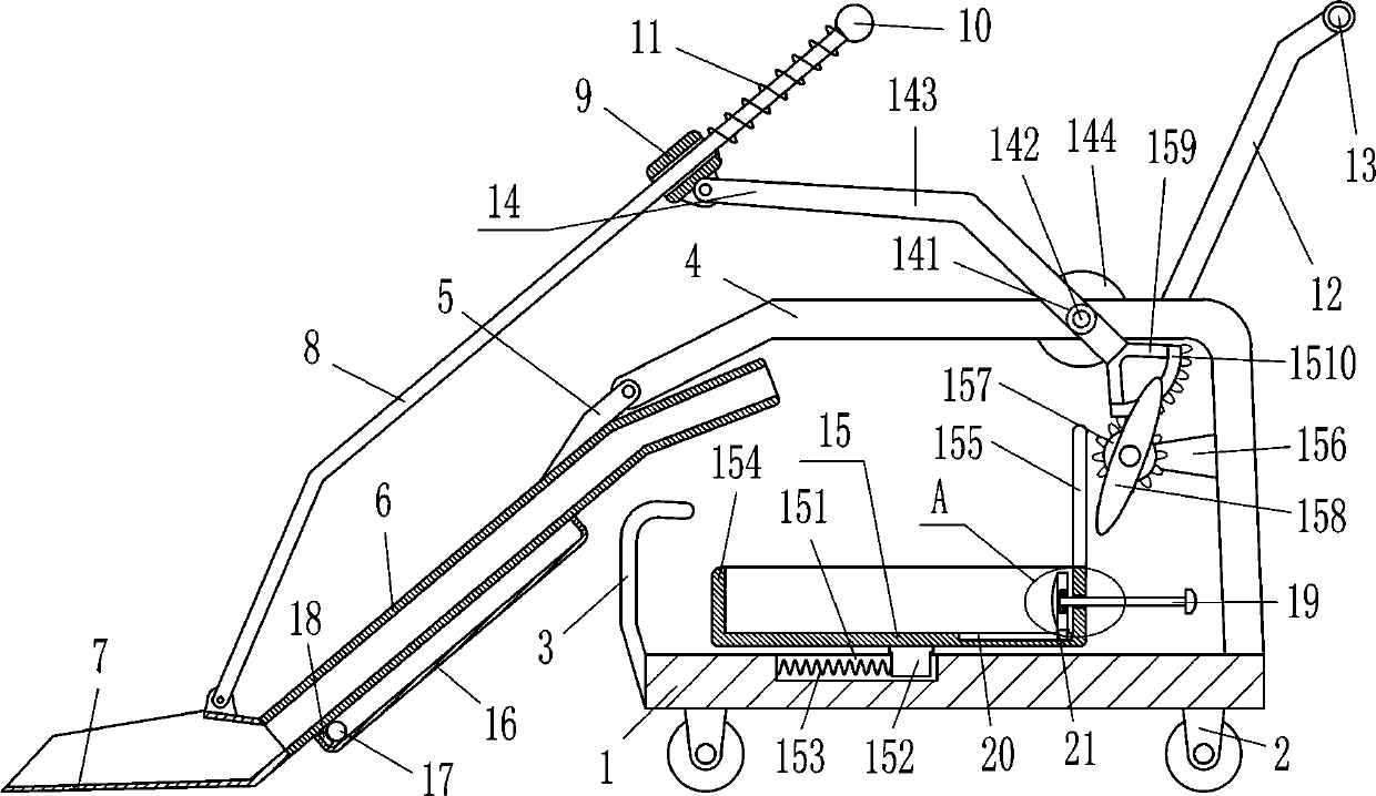
[0015] A kind of bulk sand barreling machine, such as figure 1 As shown, it includes bottom plate 1, wheel 2, 7-type baffle plate 3, 7-type frame 4, connecting rod 5, movable pipe 6, bucket 7, movable rod 8, sliding sleeve 9, limit ball 10, first spring 11. Support rod 12, grip rod 13 and driving device 14. Wheels 2 are installed symmetrically on the left and right sides of the bottom of the bottom plate 1. The bottom plate 1 is connected to the wheels 2 by bolts, which can prevent the sand bucket from falling. Type 7 The baffle plate 3 is installed on the left side of the base plate 1. The 7-type baffle plate 3 is connected to the base plate 1 through bolt connection. The top right side of the base plate 1 is fixed with the 7-type frame 4. 4 connection, the left end of the 7-type frame 4 is hinged with a connecting rod 5, and the bottom end of the connecting rod 5 is fixedly connected with a movable pipe 6 that can make the sand flow. The movable pipe 6 is located above the 7...

Embodiment 2

[0017] A kind of bulk sand barreling machine, such as figure 1 As shown, it includes bottom plate 1, wheel 2, 7-type baffle plate 3, 7-type frame 4, connecting rod 5, movable pipe 6, bucket 7, movable rod 8, sliding sleeve 9, limit ball 10, first spring 11. Support rod 12, grip rod 13 and driving device 14. Wheels 2 are installed symmetrically on the left and right sides of the bottom of the bottom plate 1, and the 7-type baffle plate 3 that can prevent the sand bucket from falling is installed on the left side of the bottom plate 1. The bottom plate 1. The right side of the top is fixed with a 7-type frame 4, the left end of the 7-type frame 4 is hinged with a connecting rod 5, and the bottom of the connecting rod 5 is fixed with a movable tube 6 that allows sand to flow. The movable tube 6 is located above the 7-type baffle 3 , the bucket 7 is installed on the left end of the movable pipe 6, the left side of the outer top of the bucket 7 is hinged with a movable rod 8, and t...

Embodiment 3

[0020] A kind of bulk sand barreling machine, such as figure 1 As shown, it includes bottom plate 1, wheel 2, 7-type baffle plate 3, 7-type frame 4, connecting rod 5, movable pipe 6, bucket 7, movable rod 8, sliding sleeve 9, limit ball 10, first spring 11. Support rod 12, grip rod 13 and driving device 14. Wheels 2 are installed symmetrically on the left and right sides of the bottom of the bottom plate 1, and the 7-type baffle plate 3 that can prevent the sand bucket from falling is installed on the left side of the bottom plate 1. The bottom plate 1. The right side of the top is fixed with a 7-type frame 4, the left end of the 7-type frame 4 is hinged with a connecting rod 5, and the bottom of the connecting rod 5 is fixed with a movable tube 6 that allows sand to flow. The movable tube 6 is located above the 7-type baffle 3 , the bucket 7 is installed on the left end of the movable pipe 6, the left side of the outer top of the bucket 7 is hinged with a movable rod 8, and t...


PUM


Abstract

The invention relates to a barrel loader, in particular to a bulk sand barrel loader. The bulk sand barrel loader aims at achieving the technical effects of being capable of replacing manual work to pour sand into a sand charging barrel, avoiding arm soreness, saving labor, and being capable of shaking the sand charging barrel to smooth the sand. According to the technical scheme, the bulk sand barrel loader comprises a bottom plate, wheels, an inverted-L-shaped baffle plate, an inverted-L-shaped frame, a connecting rod, a movable pipe, a bucket, a movable rod, a sliding sleeve, a limiting ball and the like, the wheels are symmetrically arranged on the left side and the right side of the bottom of the bottom plate, the inverted-L-shaped baffle plate capable of preventing the sand chargingbarrel from falling off is arranged on the left side surface of the bottom plate, the inverted-L-shaped frame is fixedly connected to the right side of the top of the bottom plate, and the connectingrod is hinged to the left end of the inverted-L-shaped frame. According to the sand loading barrel, sand is shoveled up by the bucket, a driving motor is started to rotate forwards, the bucket can move upwards to be in an inclined state, the sand is poured into the sand charging barrel through the movable pipe, people do not need to continuously shovel the sand into the sand charging barrel by using a shovel, labor is saved, and the problem that arm soreness influences subsequent work is avoided.

Description

technical field [0001] The invention relates to a bucket loading machine, in particular to a loose sand bucket loading machine. Background technique [0002] During building construction, sand is needed to make concrete or other construction projects, but the sand is piled up together and needs to be put into a sand bucket for transportation. Usually, people use a shovel to shovel the sand into the sand bucket , people need to constantly swing the shovel. Over time, people's arms tend to be sore and affect the follow-up work, and the sand is easy to accumulate when poured into the sand bucket. It is laborious to shake the sand bucket to make it smooth, so people will alternate Shovel up the shovel, and use the shovel to scrape the sand in the sand bucket evenly. This operation is troublesome and the labor cost is high. Contents of the invention [0003] In order to overcome the disadvantages that people need to constantly swing the shovel, people's arms are easy to be sor...

Claims


Application Information

Patent Timeline
Patent Type & Authority Applications(China)
IPC IPC(8): B65G65/04
CPCB65G65/04B65G2201/045
Inventor 陈浩
Owner 威海高新园区运营管理有限公司
Why Eureka
Eureka Blog
Learn More