Pressing type clay brick manufacturing device
A production device and pressing technology, applied in the direction of supply devices, manufacturing tools, auxiliary molding equipment, etc., can solve the problems of troublesome operation, low work efficiency, low quality, etc., and achieve the effect of convenient collection
- Summary
- Abstract
- Description
- Claims
- Application Information
AI Technical Summary
Problems solved by technology
Method used
Image
Examples
Embodiment 1
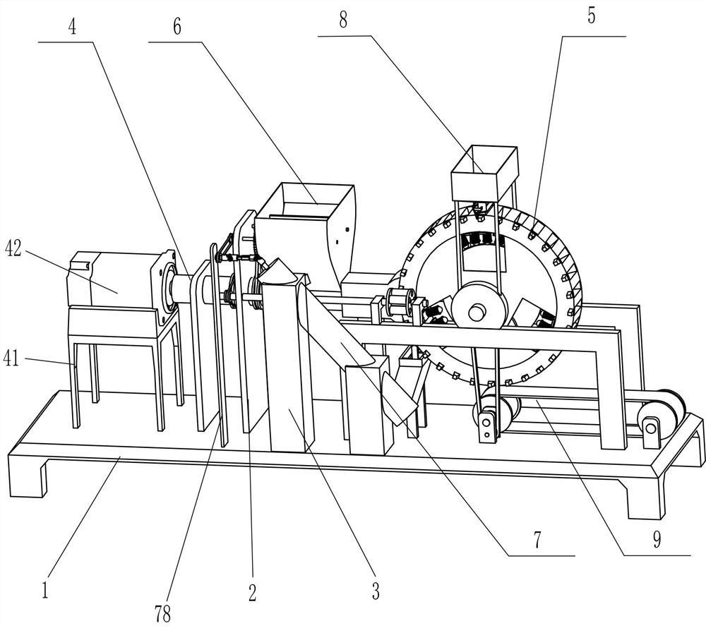
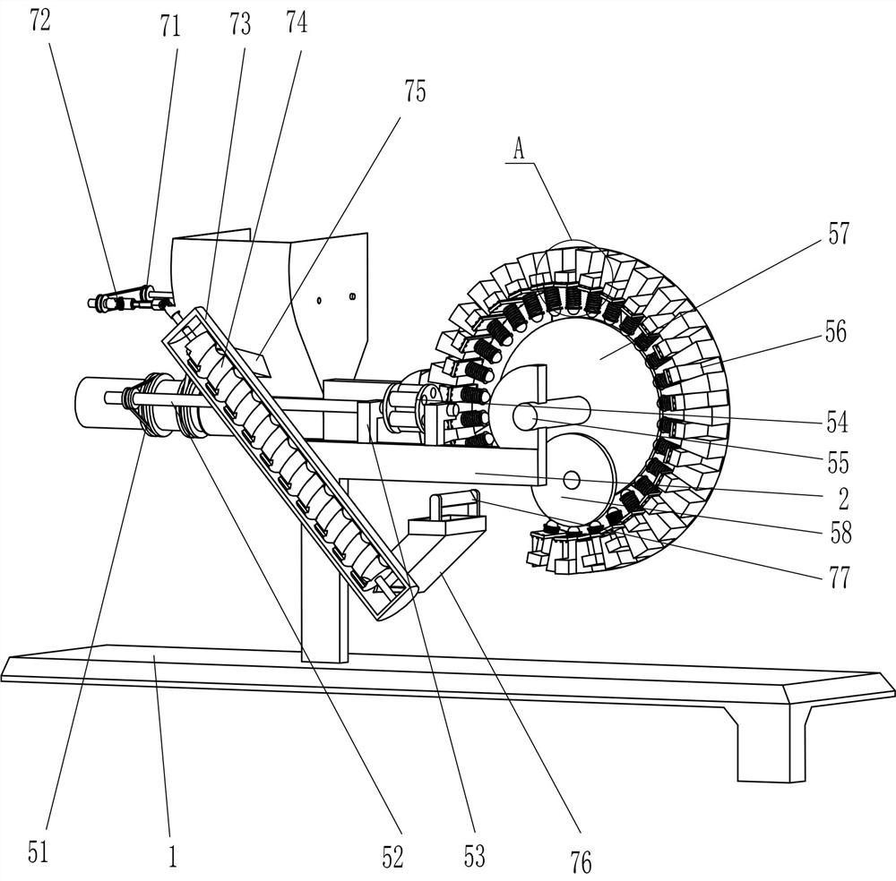
[0026] A pressed earth block making device, such as Figure 1-Figure 4 As shown, it includes a base 1, a support plate 2, a support column 3, a feeding mechanism 4 and a brick making mechanism 5. Two support plates 2 are fixed on the left side of the top of the base 1, and two A feeding mechanism 4 is arranged between the supporting column 3 and the base 1 and the supporting plate 2 , and a brick making mechanism 5 is arranged between the feeding mechanism 4 and the base 1 .
[0027] The feeding mechanism 4 includes a motor base 41, a servo motor 42, a drive roller 43, a feeding worm 44, a feeding shell 45, and a loading frame 46. Servomotor 42, between two support plates 2 tops is provided with transmission roller 43 in a rotating manner, the left end of transmission roller 43 is fixedly connected with the output shaft of servo motor 42, and the right end of transmission roller 43 is fixedly connected with feeding worm 44, and the feeding worm 44. The upper rotation type is ...
Embodiment 2
[0033] On the basis of Example 1, such as Figure 1-Figure 3 As shown, it also includes a feeding mechanism 6, which includes a second transmission assembly 61, a feeding fixed shaft 62, a first transmission gear 63 and a feeding plate 64, and the upper part of the right support plate 2 and the feeding frame The symmetrical rotation between the 46 upper parts is provided with a fixed feeding shaft 62, and a second transmission assembly 61 is connected between the left side of the rear side of the fixed shaft 62 and the right side of the transmission roller 43. The fixed shaft 62 is left A first transmission gear 63 is fixedly connected to the side circumference, and the first transmission gears 63 on the front and rear sides are meshed.
[0034] Also includes a return mechanism 7, the return mechanism 7 includes a third transmission assembly 71, a cardan shaft 72, a return shaft housing 73, a return roller 74, a return discharge frame 75, and a return feed frame 76 , a mud sc...
Embodiment 3
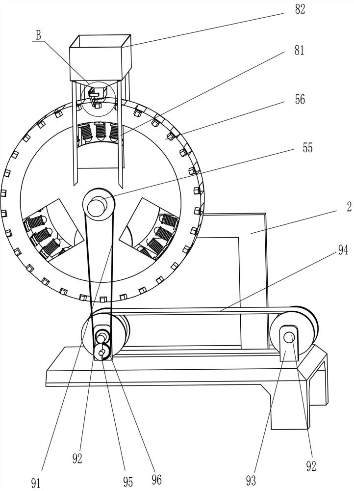
[0038] On the basis of embodiment 1 and embodiment 2, such as figure 1 , Figure 5 and Image 6 As shown, it also includes a blanking auxiliary mechanism 8, and the blanking auxiliary mechanism 8 includes a fixed pillar 81, a charging frame 82, a fixed connecting plate 83, a linkage plate 84, a perforated plate 85 and a telescopic spring 86, and an n-type plate 512 The middle of the top is symmetrically fixed with a fixed support 81, the top of the four fixed supports 81 is fixed with a charging frame 82, and the lower part of the charging frame 82 is fixed with a fixed connecting plate 83 symmetrically, and the fixed connecting plates 83 on the front and rear sides are left A linkage plate 84 is hinged between the parts, and an opening plate 85 is slidingly provided at the bottom of the loading frame 82. The left part of the opening plate 85 is located at the top of the linkage plate 84 and slides with it. A telescopic spring 86 is affixed symmetrically to the outer surface...
PUM
 Abstract
Description
Claims
Application Information
 - R&D
- Intellectual Property
- Life Sciences
- Materials
- Tech Scout
- Unparalleled Data Quality
- Higher Quality Content
- 60% Fewer Hallucinations
Browse by: Latest US Patents, China's latest patents, Technical Efficacy Thesaurus, Application Domain, Technology Topic, Popular Technical Reports.
© 2025 PatSnap. All rights reserved.Legal|Privacy policy|Modern Slavery Act Transparency Statement|Sitemap|About US| Contact US: help@patsnap.com


