Eureka AIR delivers breakthrough ideas for toughest innovation challenges, trusted by R&D personnel around the world.

Embedded type shaft coupling structure

A coupling, mounted technology, applied in the field of embedded coupling structure, can solve the problems of reducing the service life of the coupling, increasing the production cost, reducing the service life, etc., to extend the service life, improve the safety, The effect of reduced costs

Inactive Publication Date: 2019-07-19
JIANGSU ROKEE HEAVY IND TECH
View PDF6 Cites 1 Cited by
  • Summary
  • Abstract
  • Description
  • Claims
  • Application Information

AI Technical Summary

Problems solved by technology

[0002] Couplings are mechanical parts used to connect two shafts (driving shaft and driven shaft) in different mechanisms to rotate together to transmit torque. In high-speed and heavy-duty power transmission, the coupling also has buffer, reduction Vibration can improve the dynamic performance of the shaft system, and has a good performance in transmitting rotational motion. When the coupling in the prior art transmits a large torque, it generally uses a spline to connect with the shaft, and the left and right half of the coupling Undesirable sliding of the coupling on the shaft will occur. When rotating, the left and right half shafts will collide, which will not only generate noise, but also reduce the service life of the coupling.
Moreover, the existing couplings are all exposed to the outside during work. When working in rainy days or dusty areas, they may receive rain erosion or dust wear, resulting in reduced service life and increased production costs for manufacturers.

Method used


Image

  • Embedded type shaft coupling structure
  • Embedded type shaft coupling structure
  • Embedded type shaft coupling structure

Examples


Embodiment Construction

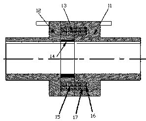
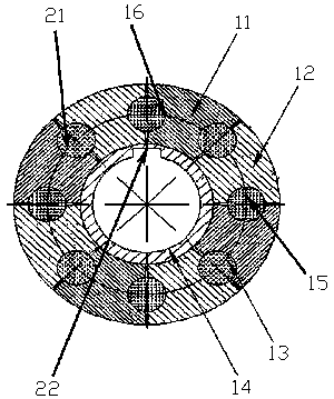
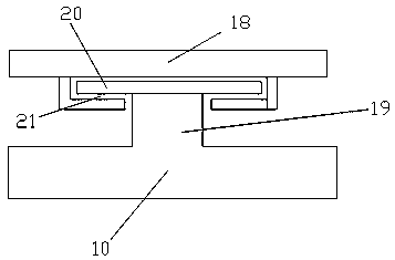
[0017] The present invention will be described in further detail below in conjunction with the accompanying drawings.

[0018] In describing the present invention, it should be understood that the terms "center", "longitudinal", "transverse", "upper", "lower", "front", "rear", "left", "right", " The orientations or positional relationships indicated by "vertical", "horizontal", "top", "bottom", "inner" and "outer" are based on the orientations or positional relationships shown in the drawings, and are only for the convenience of describing the present invention and Simplified descriptions, rather than indicating or implying that the device or element referred to must have a particular orientation, be constructed and operate in a particular orientation, and thus should not be construed as limiting the invention. In addition, the terms "first", "second", etc. are used for descriptive purposes only, and should not be understood as indicating or implying relative importance or imp...


PUM


Abstract

The invention discloses an embedded type shaft coupling structure, and relates to the technical field of shaft couplings. The embedded type shaft coupling structure comprises a shaft coupling body anda protective device, wherein the shaft coupling body comprises a driving shaft connecting part, a driven shaft connecting part, a transmission part and a locating sleeve; the driving shaft connectingpart is located at the left end and is connected to a driving shaft; the driven shaft connecting part is located at the right end and is connected to a driven shaft; the protective device is arrangedat the upper end of the shaft coupling body and is used for protecting the shaft coupling body; the protective device comprises a protective cover which is arranged at the upper end of the shaft coupling body; the upper end of the shaft coupling body extends upwards to form a boss; the boss extends respectively towards the left end and the right end to form convex brims; trough bodies fixedly connected to the convex brims are formed in the inner wall of the protective cover; and the convex brims are embedded in the trough bodies to fixedly match the protective cover with the shaft coupling body. The protective device is fixed by adopting an embedded method, and therefore, when a shaft coupling works, the shaft coupling is not damaged, and the cost of maintenance and replacement is reduced.

Description

technical field [0001] The invention relates to the technical field of shaft couplings, in particular to an embedded shaft coupling structure. Background technique [0002] Couplings are mechanical parts used to connect two shafts (driving shaft and driven shaft) in different mechanisms to rotate together to transmit torque. In high-speed and heavy-duty power transmission, the coupling also has buffer, reduction Vibration can improve the dynamic performance of the shaft system, and has a good performance in transmitting rotational motion. When the coupling in the prior art transmits a large torque, it generally uses a spline to connect with the shaft, and the left and right half of the coupling Undesired sliding of the coupling on the shaft will occur. When rotating, the left and right half shafts will collide, which will not only generate noise, but also reduce the service life of the coupling. Moreover, the existing shaft couplings are all exposed to the outside during wo...

Claims


Application Information

Patent Timeline
Patent Type & Authority Applications(China)
IPC IPC(8): F16D3/70
CPCF16D3/70
Inventor 石光洲
Owner JIANGSU ROKEE HEAVY IND TECH
Why Eureka
Eureka Blog
Learn More