Unlock instant, AI-driven research and patent intelligence for your innovation.

Design mechanism to simply adjust front-rear levelness of LED display screen

A technology of LED display and design mechanism, applied in the direction of instruments, identification devices, etc., can solve the problems of increased cost and weight, inconvenient adjustment, heavy workload, etc., to save internal space, save screws, and improve efficiency Effect

Pending Publication Date: 2019-07-19
深圳高鼎通信息技术有限公司
View PDF0 Cites 5 Cited by
  • Summary
  • Abstract
  • Description
  • Claims
  • Application Information

AI Technical Summary

Problems solved by technology

[0002] The flatness of the display surface is one of the most important factors that directly affect the display effect. At present, the LED display industry has no good way to adjust the flatness of the display surface. The light board needs to be removed to adjust the height of the magnetic fixing plate, which is not intuitive. Adjustments often require multiple disassembly and assembly operations. The workload is heavy and the efficiency is very low. There are also very few companies that install iron plates on the circuit boards. Each circuit board needs to be installed with a large iron plate and more than ten screws. And more than ten springs, which increase the cost and weight, and the box needs to add a lot of screws to avoid the position, and can't completely avoid the adjustment position, although some parts can be adjusted from the back of the box without removing the circuit board (light board) Flatness, but the adjustment is not very convenient. This industry has always had these serious defects, mainly because the research and development have not broken through these technical bottlenecks. For this reason, we propose a design mechanism that can easily adjust the flatness of the LED display screen.

Method used


Image

  • Design mechanism to simply adjust front-rear levelness of LED display screen
  • Design mechanism to simply adjust front-rear levelness of LED display screen
  • Design mechanism to simply adjust front-rear levelness of LED display screen

Examples


Embodiment Construction

[0028] In order to make the technical means, creative features, goals and effects achieved by the present invention easy to understand, the present invention will be further described below in conjunction with specific embodiments.

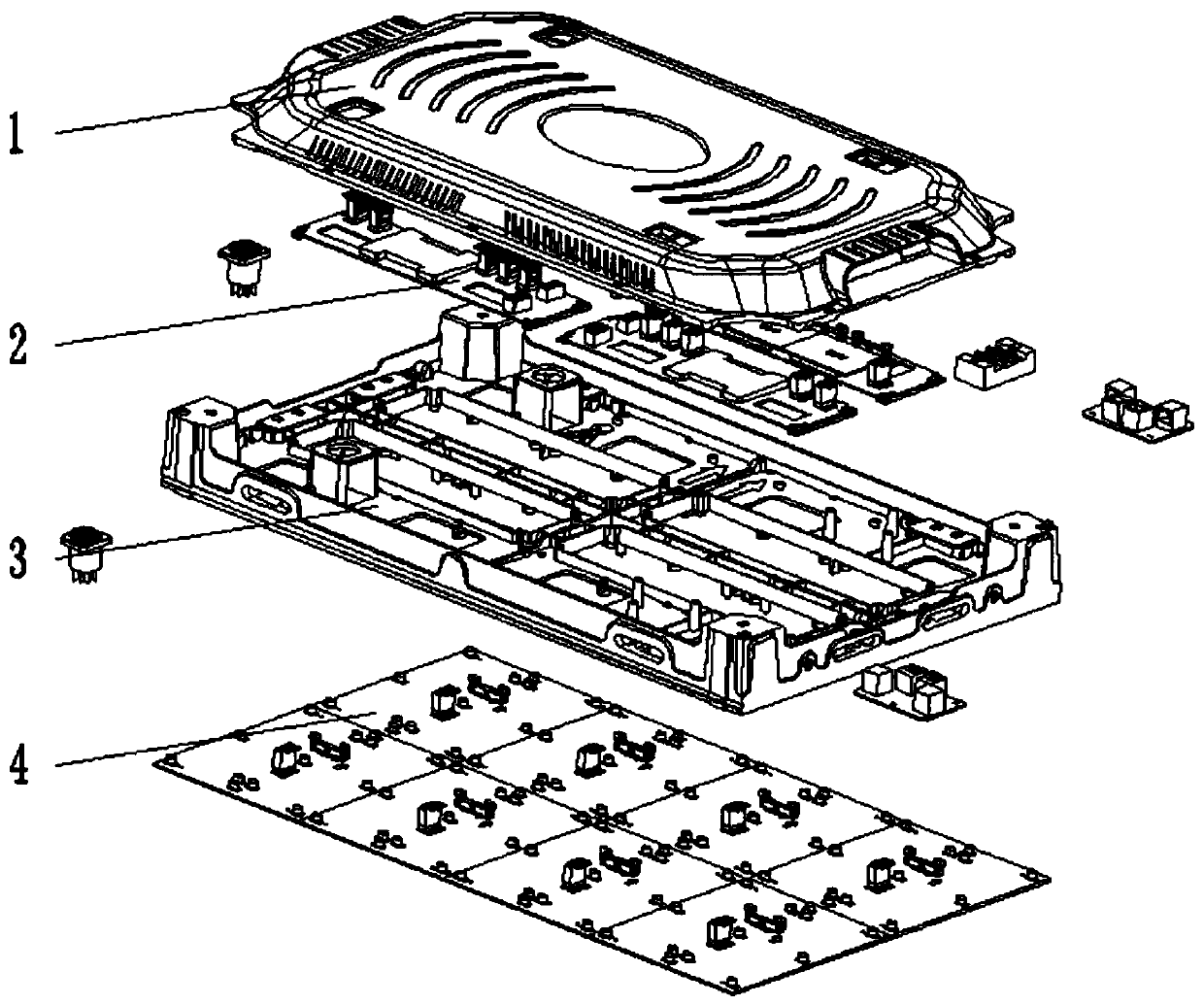
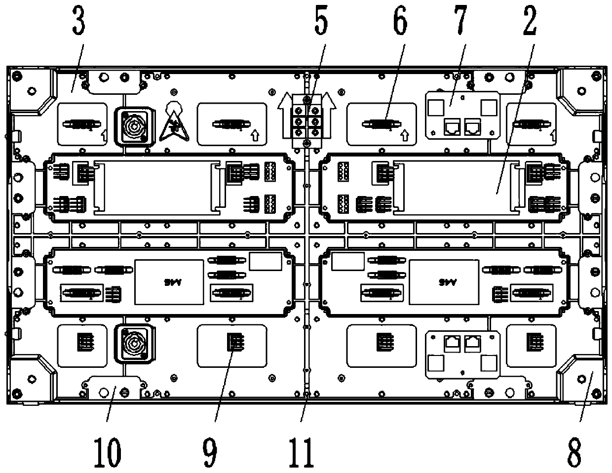
[0029] Such as Figure 1-9 As shown, a design mechanism for easily adjusting the flatness of the front and back of the LED display screen, including the back cover 1, the power signal adapter board 2, the box body 3 and the light board module 4 assembled sequentially from top to bottom, and the back cover 1 There are two network holes 101 on one side of the surface, the power signal adapter plate 2 is fixed to the surface of the box body 3 by 16-M3 screws, and the middle side of the surface of the power signal adapter plate 2 is fixed by 4-M3 screws. AC 3PIN seat 5, and a small network board 7 is fixed by 6-M3 screws at the front and rear symmetrical positions on one side of the AC 3PIN seat 5, and the four corners of the box body 3 are provided w...


PUM

PropertyMeasurementUnit
Radiusaaaaaaaaaa
Radiusaaaaaaaaaa

Abstract

The invention discloses a design mechanism to simply adjust front-rear levelness of an LED display screen. The design mechanism comprises a rear cover, a power signal adapting plate, a box body and lamp panel modules, which are fitted sequentially from top to bottom; one side of the surface of the rear cover is provided with two mesh holes. An adjustable magnetic cup structure designed herein allows the lamp panel modules to be magnetically attracted to the fixed positions of the box body; the levelness of the lamp panel is adjusted, contact with one ends of upper and lower magnetic cup holders is achieved through the tools, such as a hex lever and a screwdriver, the height of the magnetic cup holders can be adjusted from both the front and back of the box body, height differences of the lamp panel modules can be easily set to uniformity, the key is that the levelness can be visually adjusted directly on the box body without removing the modules, and the efficiency is increased by 5 folds and more; quality controllability is improved greatly; cores of the adjustable magnetic cups correspond to chip iron posts on the lamp panel modules, so that magnetic attraction is generated; eachlamp panel module can be attracted just by being placed in the box; material is saved, weight is reduced, and tedious work, such as driving screws, can be omitted.

Description

technical field [0001] The invention relates to the field of display screen adjustment mechanisms, in particular to a design mechanism that can easily adjust the flatness of the front and back of an LED display screen. Background technique [0002] The flatness of the display surface is one of the most important factors that directly affect the display effect. At present, the LED display industry has no good way to adjust the flatness of the display surface. The light board needs to be removed to adjust the height of the magnetic fixing plate, which is not intuitive. Adjustments often require multiple disassembly and assembly operations. The workload is heavy and the efficiency is very low. There are also very few companies that install iron plates on the circuit boards. Each circuit board needs to be installed with a large iron plate and more than ten screws. And more than ten springs, which increase the cost and weight, and the box needs to add a lot of screws to avoid the...

Claims


Application Information

Patent Timeline
IPC IPC(8): G09F9/33
CPCG09F9/33
Inventor 刘兰罗开文喻杰古永泉
Owner 深圳高鼎通信息技术有限公司