Key structure

A key and limit structure technology, applied in key modules, electrical components, electrical switches, etc., can solve problems such as shaking, loose components, and the position of the keycap is not fixed.

Inactive Publication Date: 2019-07-19
DARFON ELECTRONICS (SUZHOU) CO LTD +1
View PDF0 Cites 1 Cited by
  • Summary
  • Abstract
  • Description
  • Claims
  • Application Information

AI Technical Summary

Problems solved by technology

However, too much clearance often causes some components to loosen
For example, the position of the keycap is not fixed, and it will shake when it is actuated, which affects the user's feeling of pressing the keycap.
In addition, permanent deformation or damage may occur to each component during the assembly process, so that...

Method used


Image

  • Key structure
  • Key structure
  • Key structure

Examples


Embodiment Construction

[0102] In order to have a further understanding of the purpose, structure, features, and functions of the present invention, the following detailed descriptions are provided in conjunction with the embodiments.

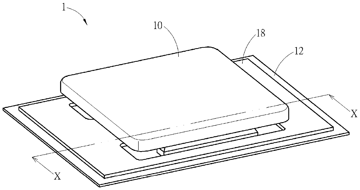
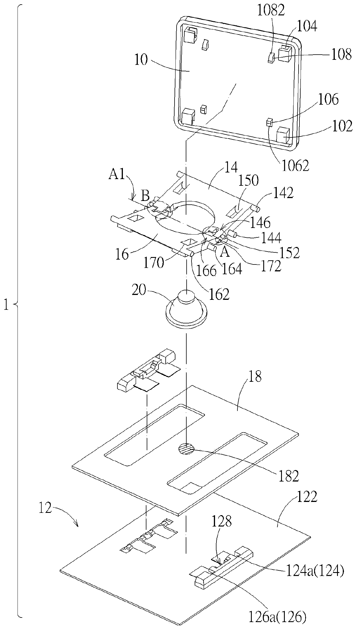
[0103] see Figure 1 to Figure 2 , figure 1 It is a schematic diagram of a button structure according to an embodiment; figure 2 for figure 1 Partial exploded view of the middle key structure. in, figure 1 It is shown that the key structure 1 according to an embodiment includes a key cap 10 , a base 12 , a first bracket 14 , a second bracket 16 , a switch circuit board 18 and an elastic reset member 20 . The base 12 is arranged under the keycap 10, the first bracket 14 and the second bracket 16 are respectively connected between the keycap 10 and the base 12, the switch circuit board 18 is placed on the base 12, and the elastic reset member 20 corresponds to the position of the switch circuit board 18. A switch 182 (shown as a hatched circle) is placed on the sw...


PUM


Abstract

The present invention provides a key structure comprising a key cap, a base and a first support and a second support that are pivotally connected to each other and connected between the key cap and the base. The key cap can move up and down relative to the base via the first support and the second support. Coordination of an axle and a C-shaped axle hole or half axle and half hole can be used forthe pivotal connection between the first support and the second support so that the assembly is easy and the pivoting structure strength is high. Limiting structures can be arranged on the first support and the second support for the key cap. The sum of the structural interference gaps is maintained within a predetermined range so that the first support and the second support can be actuated relatively smooth and are prevented from excessive wear. An abutment structure can be arranged on the supports, which can selectively interfere with the base in structure to limit the highest position of the key cap. The structural configuration is beneficial to the actuation stability of the key structure.

Description

technical field [0001] The invention relates to a mechanical key structure, in particular to a mechanical key structure in which a key cap is supported and actuated by a first bracket and a second bracket. Background technique [0002] The existing mechanical key structure has a plurality of interconnected and relatively actuating components. In order to make each component operate smoothly, a considerable gap is left between each component in principle to avoid structural interference or excessive friction during actuation. However, too much clearance often causes some components to loosen. For example, the position of the keycap is not fixed, and there will be a phenomenon of shaking when the keycap is actuated, which affects the user's feeling of pressing the keycap. In addition, permanent deformation or damage may occur to each component during the assembly process, so that the gap between each component is enlarged, which will make the above-mentioned loose phenomenon ...

Claims


Application Information

Patent Timeline
IPC IPC(8): H01H13/705
CPCH01H13/705H01H2233/074
Inventor 赵令溪
Owner DARFON ELECTRONICS (SUZHOU) CO LTD
Why Eureka
Try Eureka