Grounding connection device and grounding method

A technology of connecting device and grounding plate, applied in the direction of clip connection conductor connection, connection, measuring device, etc., can solve the problems of small contact area between grounding plate and terminal, easy rust on metal surface, not fastened in place, etc., to increase grounding The area, the structure is simple, and the effect of preventing poor grounding

Pending Publication Date: 2019-07-19
STATE GRID JIBEI ELECTRIC POWER CO LTD TANGSHAN POWER SUPPLY CO +1
View PDF9 Cites 0 Cited by
  • Summary
  • Abstract
  • Description
  • Claims
  • Application Information

AI Technical Summary

Problems solved by technology

[0002] At present, in the operation and inspection and maintenance of electric equipment, the grounding operation is very important. The existing grounding is mainly to connect the equipment to the grounding plate through the grounding wire. Usually, the terminal is fixed to the grounding plate by bolts, but the bolts are fixed. During the process, it is necessary to tighten the bolts with a wrench. This process is time-consuming and laborious, especially for operations that require multiple grounding wires to be grounded. In addition, the grounding plate and terminals are all made of metal. After a long time, the metal The surface is prone to rust, and the bolts may not be fastened in place during the fastening process, and the contact area between the grounding plate and the terminal is small. These factors may cause the wire to be grounded on the surface, but in fact it is not Forming an effective electrical connection is very likely to cause a great safety hazard to the next operation, so it is extremely important to produce a grounding connection device that can indicate the grounding effect

Method used


Image

  • Grounding connection device and grounding method
  • Grounding connection device and grounding method
  • Grounding connection device and grounding method

Examples


Embodiment Construction

[0038] Below in conjunction with accompanying drawing and embodiment the present invention will be further described:

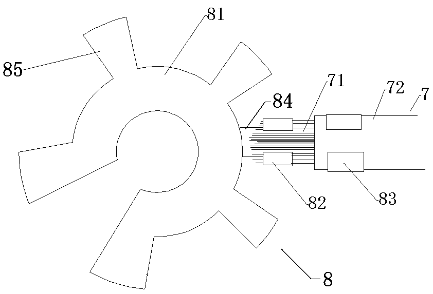
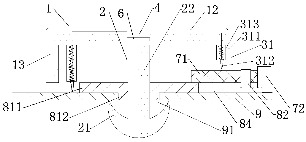
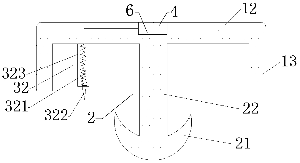
[0039] A grounding connection device, comprising a buckle device, a control module 4, an indicating part 5, a power supply 6, wires 7, terminals 8 and a grounding plate 9;

[0040] The terminal 8 includes an annular portion 81, fan blades 85, conductive copper sheets 84 and a clip body. The annular portion 81 is composed of an open ring 811 and a boss 812. The side of the open ring 811 is provided with a plurality of fans along the circumferential direction. The leaf 85 and the opening ring 811 are provided with an arc-shaped boss 812 on the lower end surface near the inner ring, the conductive copper sheet 84 is connected on the opening ring 811, and the electric wire 7 is fixed on the conductive copper sheet through the clip body;

[0041] The grounding plate 9 is arranged below the terminal 8, and the grounding plate is provided with a grounding hole 91, a...


PUM


Abstract

The invention relates to a grounding connection device and a grounding method, and belongs to the technical field of electric power grounding equipment. According to the technical scheme, a buckling device is pressed towards a circular ring part; an elastic clamping piece (21) at the bottom end of a cylinder (22) passes through the circular ring part (81) and is restored to the original shape under the elastic force of self and is in elastic contact with the lower end plane of a ground plate (9); the lower end surfaces of an open circular ring (811) and fan blades (85) are both connected withthe ground plate (9); a spring contact II (32) is in contact with the ground plate, and a spring contact I is in contact with a conductor part of an electric wire; and at the moment, if the ground plate is in high contact with an electric wire, an indicating part displays normally, and otherwise, a terminal or the ground plate needs to be further processed until the indicating part displays normally. The grounding connection device is simple in structure and convenient to use, the contact area between the terminal and the grounding plate is enlarged, rapid grounding of the electric wire can berealized, and the grounding effect can be indicated.

Description

technical field [0001] The invention relates to a grounding connection device and a grounding method, belonging to the technical field of power grounding equipment. Background technique [0002] At present, in the operation and inspection and maintenance of electric equipment, the grounding operation is very important. The existing grounding is mainly to connect the equipment to the grounding plate through the grounding wire. Usually, the terminal is fixed to the grounding plate by bolts, but the bolts are fixed. During the process, it is necessary to tighten the bolts with a wrench. This process is time-consuming and laborious, especially for operations that require multiple grounding wires to be grounded. In addition, the grounding plate and terminals are all made of metal. After a long time, the metal The surface is prone to rust, and the bolts may not be fastened in place during the fastening process, and the contact area between the grounding plate and the terminal is s...

Claims


Application Information

Patent Timeline
Patent Type & Authority Applications(China)
IPC IPC(8): H01R4/48H01R11/12H01R4/18H01R43/00H01R43/027G01R31/04
CPCH01R4/4809H01R4/4863H01R11/12H01R4/18H01R43/007H01R43/027G01R31/66
Inventor 宋世超孟繁辉李征刘天任张鹏杨坤徐建征王盛伟陈永刚
Owner STATE GRID JIBEI ELECTRIC POWER CO LTD TANGSHAN POWER SUPPLY CO
Why Eureka
Try Eureka