
Driving circuit, synchronous rectification circuit and synchronous rectification device

A technology of driving circuit and synchronous rectifier tube, applied in the field of electronics, can solve the problem of simultaneous conduction of synchronous rectifier tube, etc., and achieve the effect of improving system efficiency

Active Publication Date: 2019-07-19
SHENZHEN WINSEMI MICROELECTRONICS
View PDF5 Cites 5 Cited by
  • Summary
  • Abstract
  • Description
  • Claims
  • Application Information

AI Technical Summary

Problems solved by technology

[0003] However, when there is no direct communication between the synchronous rectifier controller and the main switch signal of the primary side, how to effectively avoid the simultaneous conduction of the power transistor on the primary side and the synchronous rectifier tube on the secondary side becomes an urgent problem to be solved

Method used


Image

  • Driving circuit, synchronous rectification circuit and synchronous rectification device
  • Driving circuit, synchronous rectification circuit and synchronous rectification device
  • Driving circuit, synchronous rectification circuit and synchronous rectification device

Examples


Embodiment Construction

[0069] In order to make the purpose, technical solution and advantages of the present application clearer, the present application will be further described in detail below in conjunction with the accompanying drawings and embodiments. It should be understood that the specific embodiments described here are only used to explain the present application, not to limit the present application.

[0070] It should be noted that when a component is referred to as being “fixed on” or “disposed on” another component, it may be directly or indirectly located on the other component. When an element is referred to as being "connected to" another element, it can be directly or indirectly connected to the other element. The terms "upper", "lower", "left", "right", "front", "rear", "vertical", "horizontal", "top", "bottom", "inner", "outer", etc. The indicated orientation or position is based on the orientation or position shown in the drawings, and is only for convenience of description, a...


PUM


Abstract

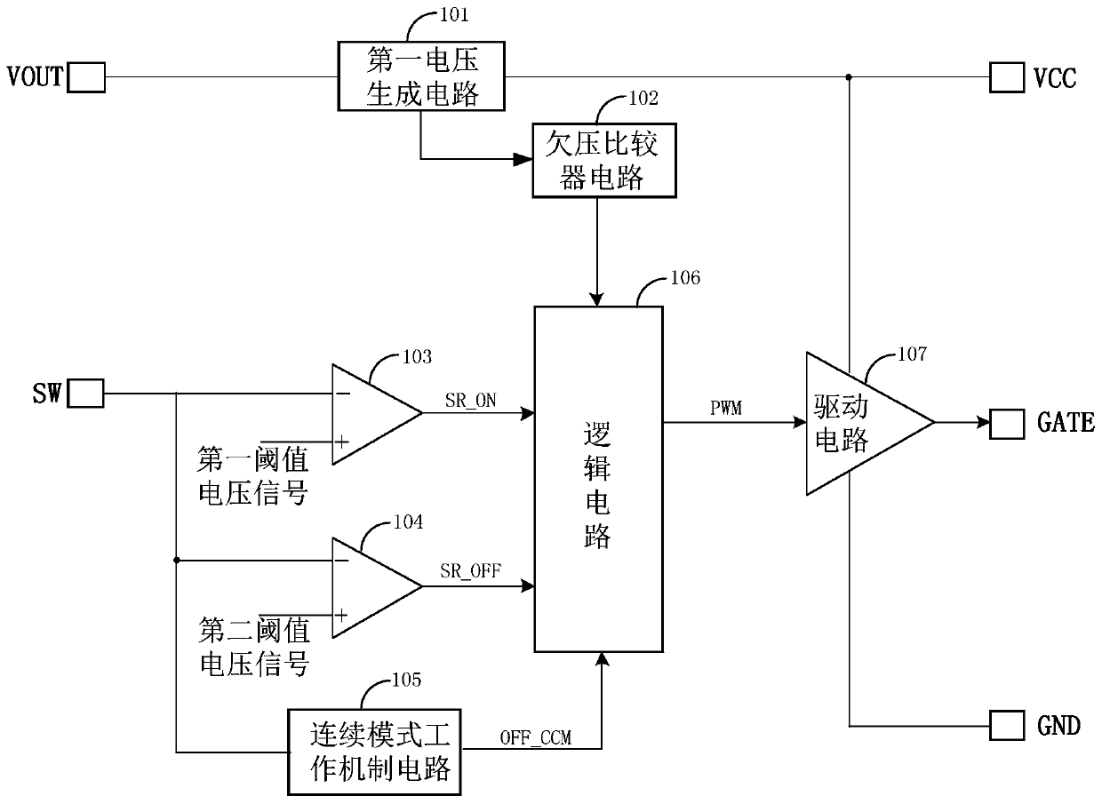
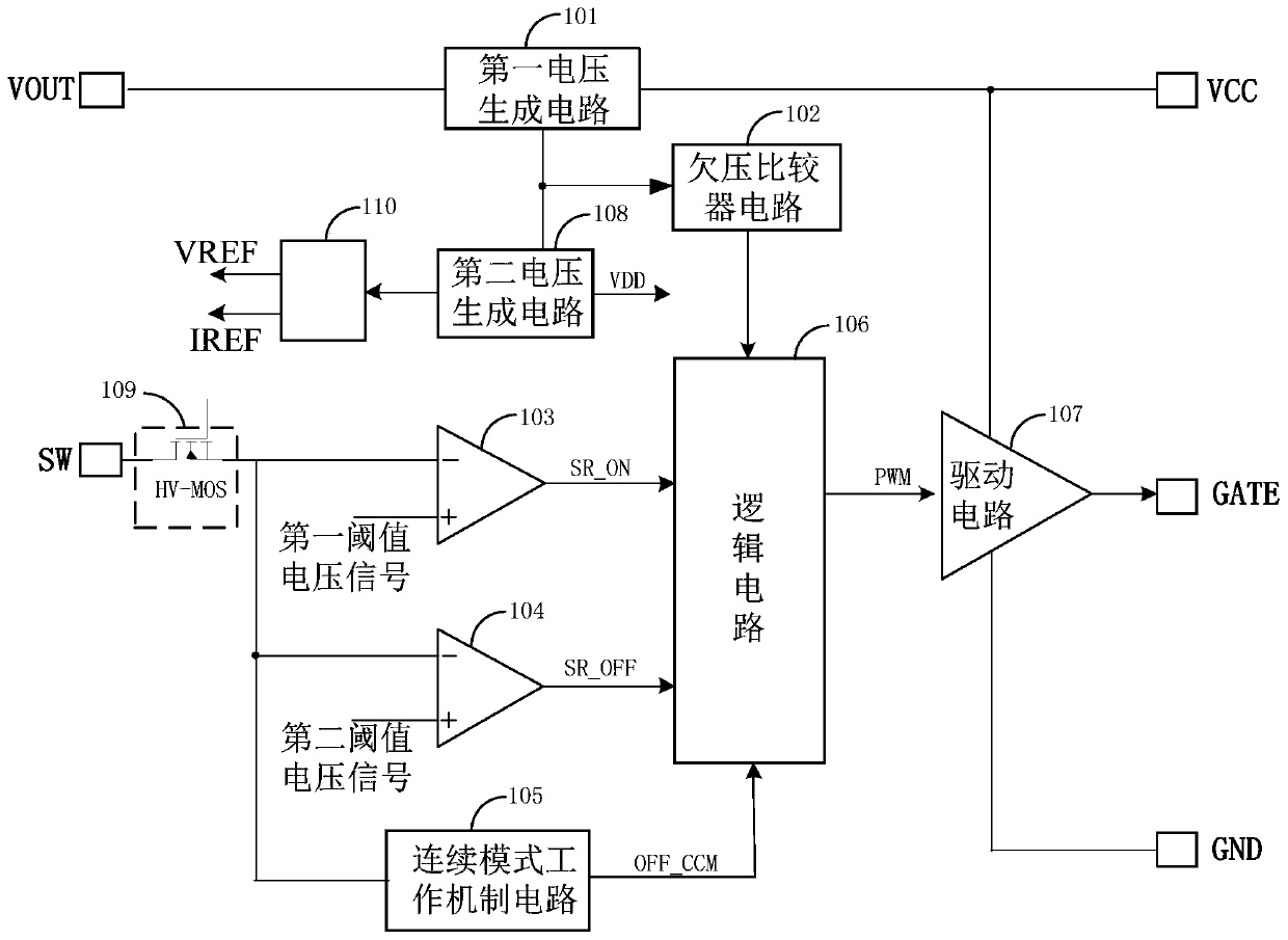
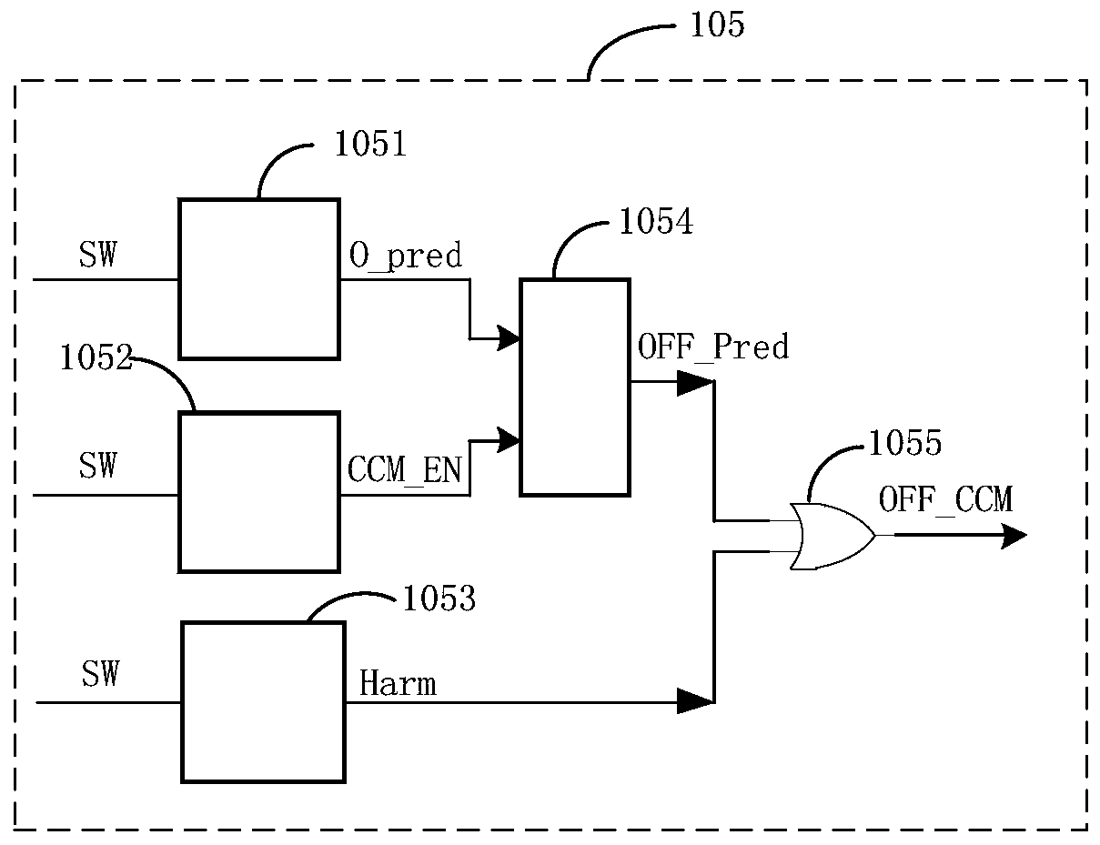
The invention is applicable to the technical field of electronics, and provides a driving circuit applied to a synchronous rectification tube, a synchronous rectification circuit and a synchronous rectification device. The driving circuit comprises a first voltage generation circuit, an under-voltage comparator circuit, a synchronous rectification tube starting comparator circuit, a synchronous rectification cutoff comparator circuit, a continuous mode working mechanism circuit, a logic circuit and a driving circuit, a corresponding driving control signal is output by detecting a drain voltagesignal and a system voltage signal of the synchronous rectification tube, and the driving of the synchronous rectification tube is achieved. With the driving circuit provided by the scheme, the starting and the cutoff of the synchronous rectification tube can be effectively controlled, a phenomenon that a primary side and a secondary side communicate with each other can be prevented no matter whether the primary side works in a DCM mode, a QR mode or a CCM mode, so that a secondary flywheeling diode can be effectively substituted by the synchronous tube, and the system efficiency is improved.

Description

technical field [0001] The embodiments of the present application belong to the field of electronic technology, and particularly relate to a drive circuit, a synchronous rectification circuit, and a synchronous rectification device applied to a synchronous rectifier. Background technique [0002] The general current source synchronous rectification drive obtains the drive signal by sampling the current flowing through the synchronous rectifier tube. When it is detected that there is current flowing through the body diode of the synchronous rectifier, a drive signal for the synchronous rectifier is generated. When the current drops to close to zero, the synchronous rectifier is turned off, so that the current cannot flow from the drain to the source of the synchronous rectifier. In this working mode, the synchronous rectifier, like the diode, can only conduct in one direction, and can be used in various converter topology circuits. Therefore, the current-driven synchronous re...

Claims


Application Information

Patent Timeline
IPC IPC(8): H02M3/335H02M1/08
CPCH02M1/08H02M3/33592Y02B70/10
Inventor 宋利军白文利
Owner SHENZHEN WINSEMI MICROELECTRONICS
Learn More