Unlock instant, AI-driven research and patent intelligence for your innovation.

Automatic dreg-removing waste liquid tank for washing ship waste gas

A waste gas washing and waste liquid pool technology, which is applied in the separation of solids from solids by air flow, chemical instruments and methods, filtration and separation, etc., can solve the problems of inability to remove waste residues, inability to classify waste residues, etc., to solve the problem of inconvenient cleaning Effect

Inactive Publication Date: 2019-07-23
唐山伟德船用设备有限公司
View PDF6 Cites 0 Cited by
  • Summary
  • Abstract
  • Description
  • Claims
  • Application Information

AI Technical Summary

Problems solved by technology

[0004] The purpose of the present invention is to solve the problem that the waste slag cannot be removed and the waste slag cannot be classified and processed, and a kind of automatic slag removal waste liquid pool for ship exhaust gas washing is proposed

Method used


Image

  • Automatic dreg-removing waste liquid tank for washing ship waste gas
  • Automatic dreg-removing waste liquid tank for washing ship waste gas
  • Automatic dreg-removing waste liquid tank for washing ship waste gas

Examples


Embodiment 1

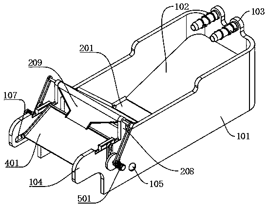
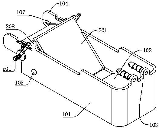
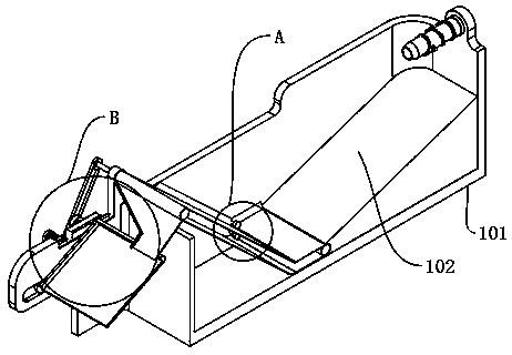
[0032]An automatic slag removal waste liquid tank for ship exhaust gas washing, including: waste liquid treatment tank 101, preliminary screening plate 102 and filter conveyor belt 201, also includes: multi-angle feeding mechanism and reciprocating transmission mechanism, waste liquid treatment tank A preliminary screening plate 102 is fixedly installed on the right side of the inside of the 101, and a feeding fixed plate 103 is fixedly installed on the front and rear sides of the upper middle part of the waste liquid treatment tank 101 on the right. The right end of the filter conveyor belt 201 is movably socketed inside the left end of the sub-board 102, and the front and rear sides of the left end of the waste liquid treatment tank 101 are fixedly connected with the left end of the limit mounting plate 104. It is fixedly connected with the front and rear sides of the left end of the filter conveyor belt 201, and the reciprocating transmission mechanism is fixedly connected w...

Embodiment 2

[0038] Embodiment 2: the difference based on Embodiment 1 is;

[0039] The inside of the right end of the filter conveyor belt 201 is movably connected with a drive wheel 202. The front and rear ends of the drive wheel 202 are fixedly connected to the inner end of the drive shaft 203, and the outer end of the drive shaft 203 is movably connected to the inner wall of the waste liquid treatment tank 101. The middle part of the filter conveyor belt 201 The front and rear sides of the upper and lower upper surfaces of the right position are movably connected with the limit wheel 204, the axis of the limit wheel 204 is fixedly connected with the inner end of the limit shaft 205, and the outer end of the limit shaft 205 is connected with the inner wall of the waste liquid treatment tank 101 Movably connected, filter conveyor belt 201 left end inside is fixedly installed with rotating wheel 206, the front and rear ends of rotating wheel 206 are fixedly connected with the inner end of ...

Embodiment 3

[0041] Embodiment 3: the difference based on embodiment 1 and 2 is;

[0042] The secondary screening mechanism includes: a secondary screening plate 401, a reciprocating horizontal shaft 402, a connecting shaft 403, a moving roller 404 and a limiting shaft 405, a secondary screening plate 401 is arranged below the outlet of the lower end of the feeding tray 209, and the secondary screening The front and rear sides above the right end of the sub-board 401 are fixedly connected to the right end of the inner side of the reciprocating horizontal shaft 402, and the lower end of the reciprocating horizontal shaft 402 is movably socketed inside the limit mounting plate 104, and the front and rear sides below the left end of the secondary screening plate 401 are connected to the The inner side of the shaft 403 is fixedly connected, and the outer side of the connecting shaft 403 is movably connected with the center of the moving roller 404. The moving roller 404 is movably installed ins...


PUM


Abstract

The invention discloses an automatic dreg-removing waste liquid tank for washing ship waste gas and belongs to the field of automatic dreg removal in a ship waste gas washing process. When the automatic dreg-removing waste liquid tank for washing the ship waste gas is used, a primary sieving plate is washed through adjusting a multi-angle feeding mechanism and one part of relatively large materials can be directly washed out along the primary sieving plate, so that the materials enter a filtering conveyor belt and are moved away in order to prevent the materials from being accumulated on the primary sieving plate; therefore, angles among a first-grade pipe, a second-grade pipe and a discharging pipe can be adjusted through starting a small-size motor and multi-angle rotation can be realized; furthermore, multi-angle washing can be carried out on the primary sieving plate and the materials cannot be accumulated on the primary sieving plate, so that the materials enter the next step.

Description

technical field [0001] The invention relates to the field of automatic slag removal for ship exhaust gas washing, in particular to an automatic slag removal waste liquid pool for ship exhaust gas washing. Background technique [0002] In modern industrial production, no matter in terms of environmental protection or resource reuse, industrial waste liquid is not allowed to be discharged directly without treatment. If untreated waste liquid is discharged at will, it will not only have a bad impact on the environment, It can even destroy the ecology and also cause a waste of effective resources. Nowadays, more and more industrial production enterprises pay attention to this problem and have added waste liquid pools. However, in the current ship exhaust gas treatment, it is necessary to achieve continuous and automatic production, so that waste materials such as filter residues generated in the filtration need to be quickly removed from the device, otherwise it will not be pos...

Claims


Application Information

Patent Timeline
IPC IPC(8): B01D29/01B01D29/94B07B9/00
CPCB01D29/01B01D29/94B07B9/00
Inventor 崔立军吴庆林段家贵吴加成赵立生王伟王鹏
Owner 唐山伟德船用设备有限公司