
A method of controlling a tempering machine and an electro-hydraulic servo system for controlling the tempering machine

A technology of electro-hydraulic servo system and tempering machine, applied in the field of electro-hydraulic servo system, can solve problems such as work roll surface damage, achieve the effect of improving surface quality, avoiding work roll surface damage, and avoiding work roll surface damage

Active Publication Date: 2021-04-30
SHOUGANG JINGTANG IRON & STEEL CO LTD
View PDF7 Cites 0 Cited by
  • Summary
  • Abstract
  • Description
  • Claims
  • Application Information

AI Technical Summary

Problems solved by technology

[0003] The present invention provides a method for controlling a temper machine and an electro-hydraulic servo system for controlling the temper machine, so as to solve or partially solve the problem of damage to the work roll surface of the temper machine in the process of closing the frame in the prior art problem technical problem

Method used


Image

  • A method of controlling a tempering machine and an electro-hydraulic servo system for controlling the tempering machine
  • A method of controlling a tempering machine and an electro-hydraulic servo system for controlling the tempering machine
  • A method of controlling a tempering machine and an electro-hydraulic servo system for controlling the tempering machine

Examples


Embodiment 1

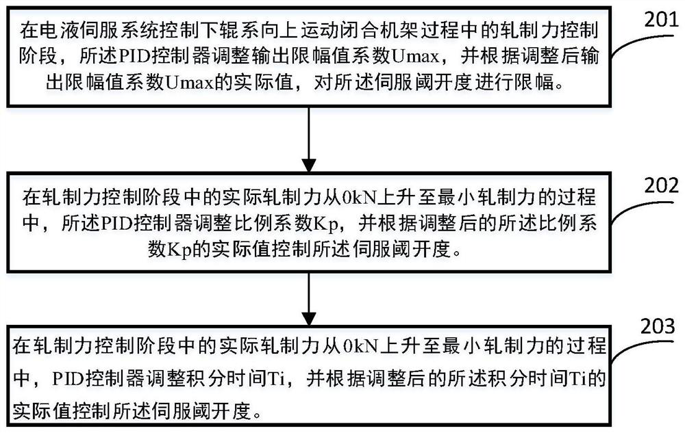
[0029] In the embodiment of the present invention, the tempering machine is first introduced. Specifically, the tempering machine includes a frame composed of an upper roller system and a lower roller system, and an electro-hydraulic servo system that controls the opening and closing of the frame; The hydraulic servo system includes a proportional-integral-derivative PID controller that adjusts the servo threshold opening of the electro-hydraulic servo system.

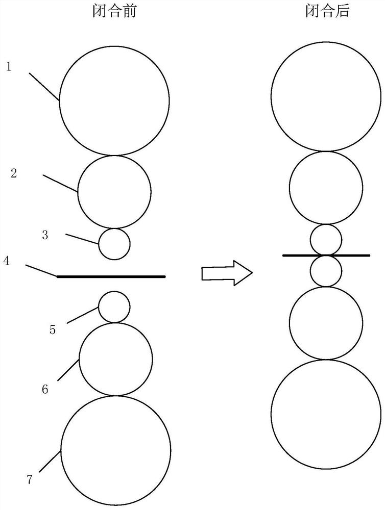
[0030] The continuous annealing and tempering mill of the present embodiment is a single-stand six-high rolling mill structure, and the stand structure is as follows: figure 1 shown, where:

[0031] Upper roll system: 1. Upper support roll, 2. Upper intermediate roll, 3. Upper working roll;

[0032] Lower roll system: 5. Lower work roll, 6. Lower intermediate roll, 7. Lower support roll;

[0033] Middle part: 4. Strip steel.

[0034] The tempering machine adopts the single-rotation transmission of the lower support ...

Embodiment 2

[0064] Based on the same inventive concept, this embodiment provides an electro-hydraulic servo system for controlling a leveling machine. Firstly, for the tempering machine, the tempering machine includes a frame composed of an upper roller system and a lower roller system; the electro-hydraulic servo system is used to control the opening and closing of the frame. For the specific working principles, please refer to the descriptions in the above embodiments, which will not be repeated in this embodiment.

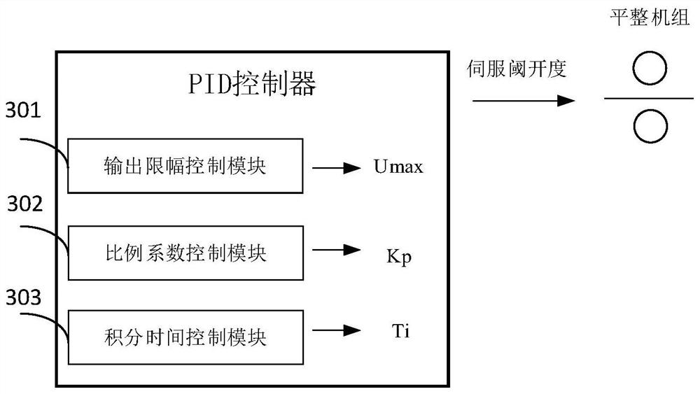
[0065] image 3 It is a schematic diagram of the electro-hydraulic servo system for controlling the tempering machine, the electro-hydraulic servo system includes a PID controller for adjusting the servo threshold opening of the electro-hydraulic servo system, and the PID controller includes: an output limiter control module 301, used for adjusting the output limit value coefficient Umax during the rolling force control stage in the process of the electro-hydraulic servo s...


PUM


Abstract

The invention aims at the technical problem of damage to the surface of the work rolls during the frame closing process after the work rolls are replaced by the temper machine, and provides a control method for the temper machine: the temper machine consists of an upper roll system and a lower roll A rack composed of a system and an electro-hydraulic servo system that controls the opening and closing of the rack, the electro-hydraulic servo system includes a proportional-integral-differential PID controller that adjusts the servo threshold opening of the electro-hydraulic servo system; in the electro-hydraulic servo system In the rolling force control stage during the process of controlling the upward movement of the lower roll system to close the stand, the PID controller adjusts the output limiting value coefficient Umax to limit the opening of the servo threshold to reduce the contact between the rolls and the strip during the closing process of the skin pass mill. The inertial impact force generated during contact avoids the roll surface damage of the newly replaced work roll during the closing process, thereby eliminating the "transverse roll mark" defect on the strip surface during start-up production, and improving the surface quality of the strip.

Description

technical field [0001] The present application relates to the technical field of iron and steel metallurgy, in particular to a method for controlling a tempering machine and an electro-hydraulic servo system for controlling the tempering machine. Background technique [0002] A 2230 continuous annealing production line uses a six-roller CVC skin pass mill. When producing strips with a width of more than 1800mm or high surface grade products, the work rolls need to be replaced, or the work rolls should be replaced during daily maintenance. After the replacement is completed, the frame should be closed. However, after the frame was closed, the roll surface of the newly replaced work roll was damaged, which led to the "horizontal roll mark" defect on the strip surface when the production was started, which seriously affected the surface quality of the strip, and a large amount of transition material was needed to eliminate it, seriously It affects the scheduling and production ...

Claims


Application Information

Patent Timeline
Patent Type & Authority Patents(China)
IPC IPC(8): B21B37/62
CPCB21B37/62
Inventor 张益滔常生财李文波王艳强刘永超张进王晨刚李国辉王硕王立朋
Owner SHOUGANG JINGTANG IRON & STEEL CO LTD
Learn More