Chamfering device for polyethylene plastic lined composite pipe

A technology of chamfering device and composite pipe, which is applied in metal processing and other directions, can solve the problems of reducing work efficiency, low water absorption, increasing production cost and working time, etc., and achieves the effect of accelerating rounding cutting and improving work efficiency.

Pending Publication Date: 2019-07-23
HENAN LIANSU IND
View PDF1 Cites 0 Cited by
  • Summary
  • Abstract
  • Description
  • Claims
  • Application Information

AI Technical Summary

Problems solved by technology

[0002] Polyethylene is a thermoplastic resin obtained by polymerization of ethylene. In industry, it also includes copolymers of ethylene and a small amount of α-olefin. Polyethylene is odorless, non-toxic, feels like wax, and has excellent low temperature resistance. Chemical Good stability, resistant to most acid and alkali erosion, insoluble in common solvents at room temperature, low water absorption, excellent electrical insulation, often used to make plastic-lined pipes, the traditional polyethylene-lined plastic pipe chamfering device has many shortcomings, For example, CN201720399548.7 includes a workbench and a driving motor installed on the workbench, the base plate is fixedly connected with four first cutter heads and four second cutter heads, and the four first cutter heads and the The two cutter heads are installed alternately and the cutting edge of the first cutting head faces the second cutting edge of the second cutting head. Although it is possible to chamfer the inner and outer pipes of the polyethylene-lined plastic pipe at the same time, it cannot meet the requirements for different diameters and different specifications. Chamfering and cutting of plastic-lined pipes, which will increase production costs and working hours, and reduce work efficiency

Method used


Image

  • Chamfering device for polyethylene plastic lined composite pipe
  • Chamfering device for polyethylene plastic lined composite pipe
  • Chamfering device for polyethylene plastic lined composite pipe

Examples


Embodiment 1

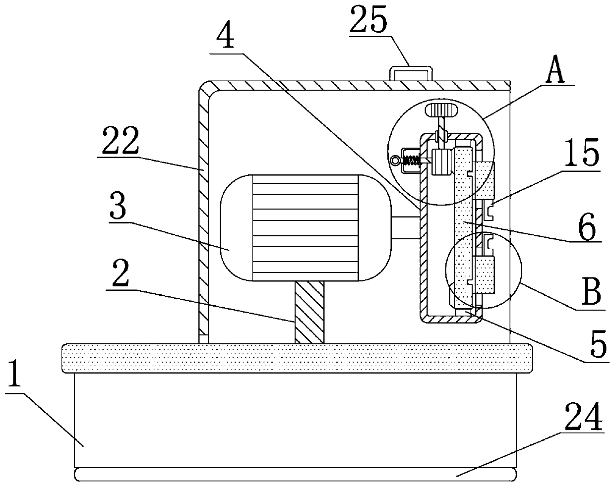
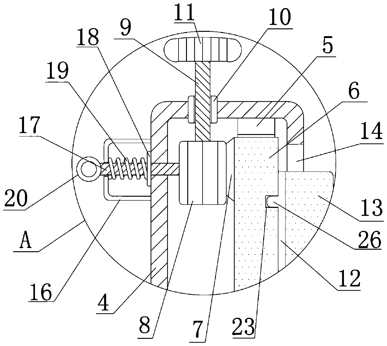
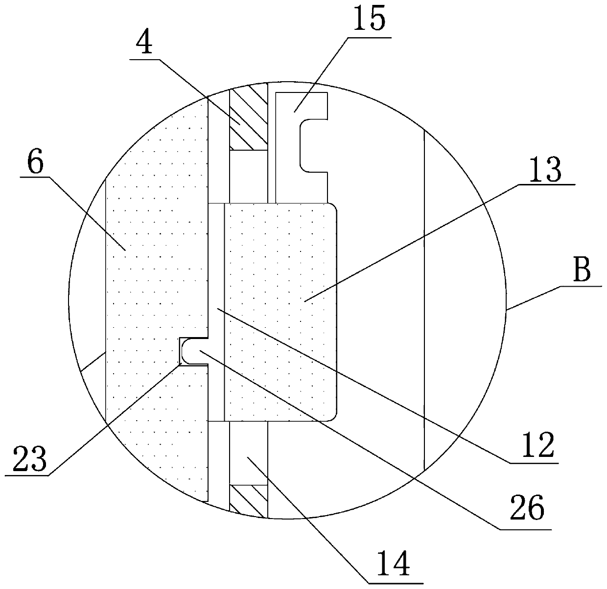
[0033] See Figure 1-6 , A polyethylene lined plastic composite pipe chamfering device, including a base 1, the bottom of the base 1 is processed with a rubber pad 24, the rubber pad 24 is used to prevent the device from moving, making the device more stable during operation, the top of the base 1 is processed with The inner wall of the mounting groove 21 is slidably clamped with a top cover 22, the top cover 22 is used to protect the device from dust, and the top of the top cover 22 is fixedly connected with a curved rod 25, which makes the top cover 22 easy to slide. The top of the base 1 is fixedly welded with a bracket 2, and the top of the bracket 2 is fixed with a motor 3. The model of the motor 3 is ECMA-E11320RS, the output end of the motor 3 is fixed with a round box 4, and the motor 3 rotates to drive the round box 4 to rotate As a primary transmission, the inner wall of the round box 4 is rotatably connected with a circular plate 6 through the first bearing 5. The bo...


PUM


Abstract

The invention relates to the technical field of chamfering devices for a polyethylene plastic lined composite pipe, in particular to the chamfering device for the polyethylene plastic lined compositepipe. The chamfering device for the polyethylene plastic lined composite pipe comprises a base, wherein a support is arranged at the top of the base, a motor is arranged at the top of the support, theoutput end of the motor is connected with a round box, the inner wall of the round box is rotationally connected with a round plate through a first bearing, the round box is provided with a secondarytransmission mechanism which is connected with the bottom surface of the round plate, the round box is provided with a limiting mechanism for limiting the secondary transmission mechanism, a slidingchute is formed in the front surface of the round plate, a square plate is movably arranged in the sliding chute, a through hole is formed in the round box, a transverse plate is fixedly arranged above the square plate and protrudes out of the through hole, and a chamfering cutter is arranged on the transverse plate. According to the chamfering device, the polyethylene plastic lined pipes with different bores and different specifications can be subjected to chamfering cutting, so that the production cost and the working time are reduced, and the working efficiency is improved.

Description

Technical field [0001] The invention relates to the technical field of a chamfering device for a polyethylene-plastic-lined composite pipe, in particular to a chamfering device for a polyethylene-plastic-lined composite pipe. Background technique [0002] Polyethylene is a thermoplastic resin made by polymerization of ethylene. In industry, it also includes copolymers of ethylene and a small amount of α-olefin. Polyethylene is odorless, non-toxic, feels like wax, and has excellent low temperature resistance. Good stability, resistance to most acids and alkalis, insoluble in general solvents at room temperature, low water absorption, and excellent electrical insulation. It is often used to make plastic-lined pipes. Traditional polyethylene-lined plastic pipe chamfering devices have many shortcomings. For example, CN201720399548.7, including a workbench and a drive motor installed on the workbench, the substrate is fixedly fixed with four first cutter heads and four second cutter h...

Claims


Application Information

Patent Timeline
Patent Type & Authority Applications(China)
IPC IPC(8): B26D3/16B26D7/26
CPCB26D3/166B26D7/2628
Inventor 代营伟李锦松
Owner HENAN LIANSU IND
Why Eureka
Try Eureka