Cream preparing system

A technology for preparing systems and creams, which can be applied in the directions of liquid materials, packaging, packaging items, etc., and can solve problems such as inability to distribute and package creams

Active Publication Date: 2019-07-23
蔓之研(上海)生物科技有限公司
View PDF8 Cites 7 Cited by
  • Summary
  • Abstract
  • Description
  • Claims
  • Application Information

AI Technical Summary

Problems solved by technology

However, this equipment cannot dispense and pack thick and v

Method used


Image

  • Cream preparing system
  • Cream preparing system
  • Cream preparing system

Examples


specific Embodiment approach 1

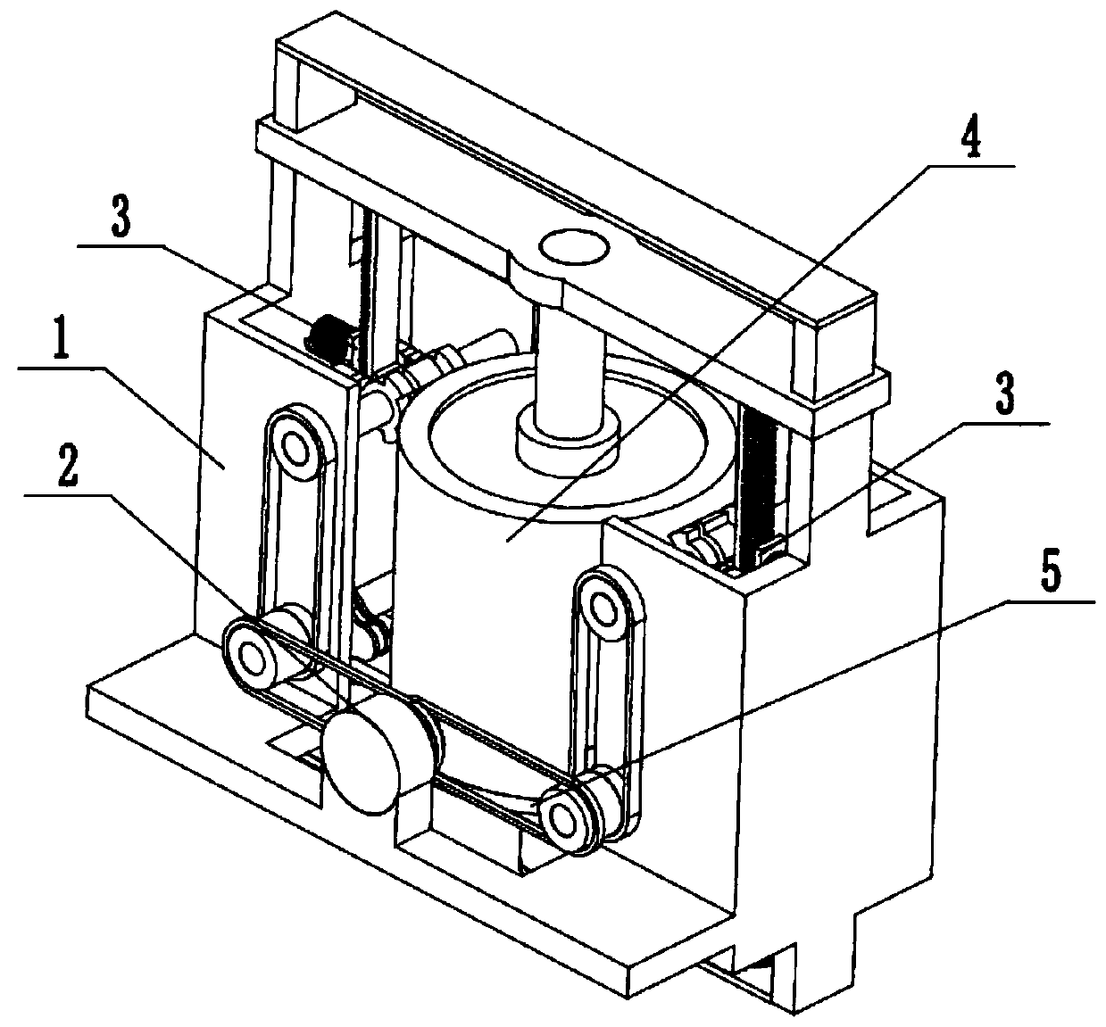
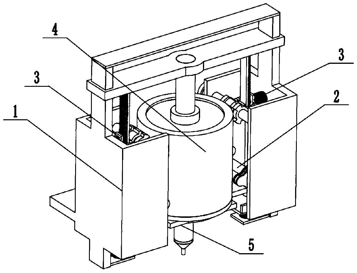
[0033] Such as Figure 1 to Figure 13 As shown, a face cream preparation system includes an adding fixed frame 1, an adding driver 2, two blocking fixing devices 3, a storage adding cylinder 4 and a base stable adding device 5, and the rear end of the adding driver 2 is fixedly connected to the Add on the fixed rack 1, the front end of the added driver 2 is rotatably connected in the added fixed rack 1, the upper end of the added driver 2 is slidably connected on the added fixed rack 1, and the left and right ends of the added driver 2 are respectively connected with two blocking The fixing device 3 is connected to the transmission, and the two blocking fixing devices 3 are respectively fixedly connected to the left and right ends of the inner wall of the adding fixed frame 1, and the upper end of the storage adding tube 4 is connected to the adding driver 2 through screw fit, and the lower end gap of the storage adding tube 4 Cooperate with the upper end of the base stable ad...

specific Embodiment approach 2

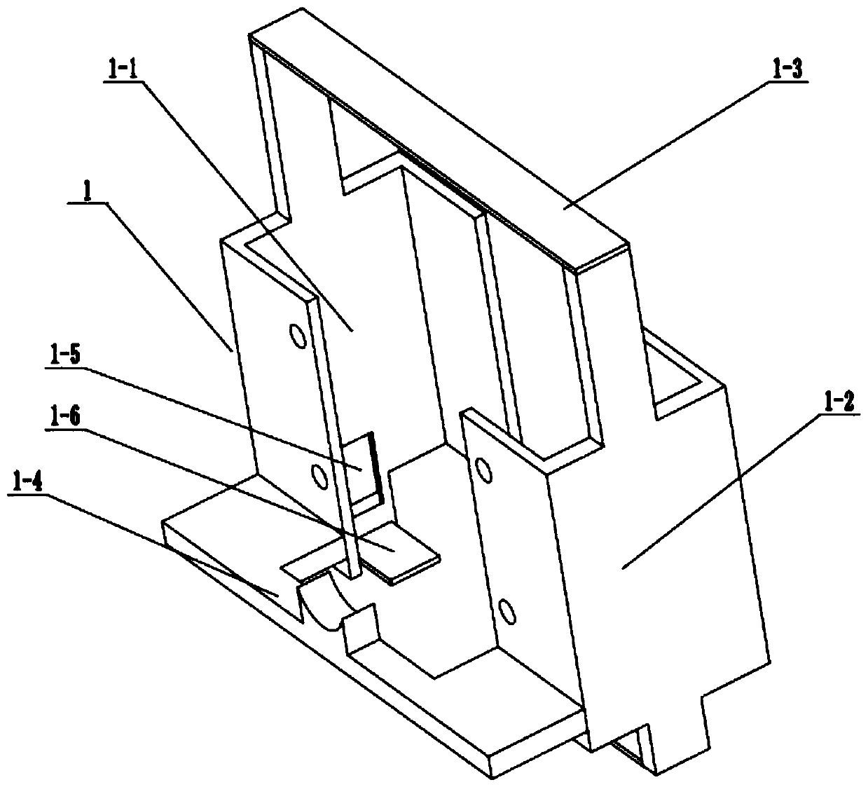
[0035] Such as Figure 1 to Figure 13 As shown, this embodiment will further illustrate Embodiment 1. The described additional fixed frame 1 includes a left fixed frame 1-1, a right fixed frame 1-2, an upper connection plate 1-3, a motor fixed plate 1-4, Two T-shaped inner chutes 1-5 and two fixed bottom plates 1-6, the left and right ends of the upper connecting plate 1-3 are respectively fixedly connected to the left fixed frame 1-1 and the right fixed frame 1-2 On the upper end, the front end of the motor fixing plate 1-4 is fixedly connected to the rear ends of the left fixing frame 1-1 and the right fixing frame 1-2, and two T-shaped inner chute 1-5 are respectively arranged on the inner wall of the left fixing frame 1-1 The left side and the right side of the inner wall of the right fixed frame 1-2, two fixed bottom plates 1-6 are respectively fixedly connected to the lower ends of the left fixed frame 1-1 and the right fixed frame 1-2.

specific Embodiment approach 3

[0037] Such as Figure 1 to Figure 13 As shown, this embodiment will further illustrate the second embodiment. The additional driver 2 includes a servo motor 2-1, a central double-row pulley 2-2, a left double-row pulley 2-3, and a right double-row pulley 2-4. , left drive shaft 2-5, right drive shaft 2-6, two pulleys 2-7, two upper shafts 2-8, two intermittent three-fan drive gears 2-9 and four intermittent three-fan drive discs 2- 10. The servo motor 2-1 is fixedly connected to the motor fixing plate 1-4, the central double-row pulley 2-2 is fixedly connected to the output shaft of the servo motor 2-1, and the central double-row pulley 2-2 passes through the belt The transmission is connected to the left double-row pulley 2-3 and the right double-row pulley 2-4, and the left double-row pulley 2-3 and the right double-row pulley 2-4 are respectively fixedly connected to the left drive shaft 2-5 and the right drive shaft 2-6 The rear end of the left drive shaft 2-5 and the ri...


PUM


Abstract

The invention relates to the field of cream production, in particular to a cream preparing system. The cream preparing system comprises an adding fixed rack, an adding driver, two blocking fixing devices, a storage adding cylinder and a base stable adding device; the rear end of the adding driver is fixedly connected to the adding fixed rack, the front end of the adding driver is rotatably connected into the adding fixed rack, the upper end of the adding driver is in sliding connection to the adding fixed rack, the left end and the right end of the adding driver are attached to the two blocking fixing devices for transmission, and the two blocking fixing devices are fixedly connected to the left end and the right end of the inner wall of the adding fixed rack. The cream preparing system has the beneficial effects that through the intermittent motion, barreled produced thick cream with the large viscosity is automatically added into a packaging bottle in an equal-size and equal-amount manner, it is ensured that cream in a packaging bottle is quantitative and equal in size, and leakage is avoided.

Description

technical field [0001] The invention relates to the field of face cream production, in particular to a face cream preparation system. Background technique [0002] Because of the high consistency of face cream, when the face cream is quantitatively packaged, it is easy to cause uneven components; the patent number is CN201721816823.7, which discloses a face cream preparation and drying device, including an electrical box and a main body of the drying device. A finished product collection box is movably installed on the outer surface of the front end, and a push-pull handle is fixedly installed on the front outer surface of the finished product collection box, rollers are movably installed on the lower end outer surface of the finished product collection box, and the front end outer surface of the electrical box is close to the finished product collection box A folding plate is installed movable under the electric box, and a supporting leg is fixedly installed on the outer su...

Claims


Application Information

Patent Timeline
IPC IPC(8): B65B3/30B65B3/08
CPCB65B3/08B65B3/30
Inventor 李安强
Owner 蔓之研(上海)生物科技有限公司
Why Eureka
Try Eureka