Mechanically connected aluminum alloy beam-column joint structure and assembly method thereof

A beam-column joint, aluminum alloy technology, applied in building structures, buildings, etc., can solve the problems of reduced energy dissipation capacity, reduced aluminum alloy strength, weakened rigidity, etc., to improve energy consumption and seismic performance, improve integrity and Strength, effects of increasing stiffness and strength

Pending Publication Date: 2019-07-23
FUJIAN UNIV OF TECH
View PDF0 Cites 3 Cited by
  • Summary
  • Abstract
  • Description
  • Claims
  • Application Information

AI Technical Summary

Problems solved by technology

For aluminum alloy structures, welding is still unavoidable in previous projects. Welding will reduce the strength, stiffness and energy dissipation capacity of aluminum alloys; when aluminum alloy beam-column joints are connected, beams, columns, connectors, stiffeners and The rigidity of the overall joint is small, the deformation is large, it is difficult to meet the force requirements, the seismic performance is insufficient, and there are problems that it cannot be quickly installed and accurately positioned

Method used


Image

  • Mechanically connected aluminum alloy beam-column joint structure and assembly method thereof
  • Mechanically connected aluminum alloy beam-column joint structure and assembly method thereof
  • Mechanically connected aluminum alloy beam-column joint structure and assembly method thereof

Examples


Embodiment Construction

[0032] In order to make the above-mentioned features and advantages of the present invention more comprehensible, the following specific embodiments are described in detail with reference to the accompanying drawings, but the present invention is not limited thereto.

[0033] refer to Figure 1 to Figure 11

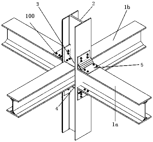
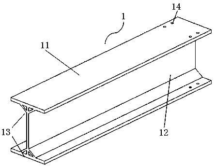
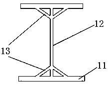
[0034] A mechanically connected aluminum alloy beam-column joint structure, including an I-shaped column 2 composed of a column web 22 and a column flange 21 vertically arranged at both ends of the column web and integrally formed with the column web. The column flanges on both sides are respectively provided with I-shaped transverse beams 1a, and the upper and lower sides of the connecting ends of the transverse beams are respectively provided with corner pieces 5, and the corner pieces are respectively connected to the column flanges, Transverse beams are connected, and the front and rear sides of the column are respectively provided with I-shaped longitudinal beams 1b...


PUM


Abstract

The invention relates to the field of civil engineering, in particular to a mechanically connected aluminum alloy beam-column joint structure and an assembly method thereof. The mechanically connectedaluminum alloy beam-column joint structure comprises I-shaped columns composed of column webs and column flanges which are vertically arranged at both ends of the column webs and integrally formed with the column webs, I-shaped transverse beams are arranged on the column flanges on the two sides of the columns correspondingly, angular shaped parts are arranged on the upper sides and the lower sides of the connecting ends of the transverse beams, the angular shaped parts are connected with the column flanges and the transverse beams through connecting bolts correspondingly, the concave parts,formed by matching the column webs and the column flanges, on the front sides and the rear sides of the columns are internally connected with I-shaped longitudinal beams correspondingly, groove-shapedribs are arranged on the upper sides and the lower sides of the connecting ends of the longitudinal beams correspondingly, and the groove-shaped ribs are connected with the longitudinal beams and thecolumns through connecting bolts correspondingly. According to the beam-column joint structure and the assembly method thereof, the influence of welding diagonal aluminum connecting parts and columnwelding stiffening ribs on the properties of aluminum alloy materials can be effectively avoid, and the integrity and strength of aluminum alloy beam-column joints are improved to a great extent.

Description

technical field [0001] The invention relates to the field of civil engineering, in particular to a mechanically connected aluminum alloy beam-column node structure and an assembly method. Background technique [0002] Aluminum alloy has the advantage of being easy to extrude, can produce any shape, and is easier to make more complex sections. Due to its own material characteristics, aluminum alloy has strong corrosion resistance, beautiful appearance and strong durability, and has broad application prospects in the field of civil engineering. For aluminum alloy structures, welding is still unavoidable in previous projects. Welding will reduce the strength, stiffness and energy dissipation capacity of aluminum alloys; when aluminum alloy beam-column joints are connected, beams, columns, connectors, stiffeners and The rigidity of the overall joint is small, the deformation is large, it is difficult to meet the force requirements, the seismic performance is insufficient, and t...

Claims


Application Information

Patent Timeline
IPC IPC(8): E04B1/58E04B1/24
CPCE04B1/2403E04B2001/2406E04B2001/2418E04B2001/2415
Inventor 张铮廖仁生林奂斌王昊邹铮轩施昶泽罗齐芬
Owner FUJIAN UNIV OF TECH
Why Eureka
Try Eureka