A gear shaft structure

A technology of gear shafts and gears, which is applied in the direction of belts/chains/gears, shafts, couplings, etc., and can solve problems such as the inability to fix the gear shaft center and easy deviation

Active Publication Date: 2020-07-07
厦门众力达机械有限公司
View PDF5 Cites 0 Cited by
  • Summary
  • Abstract
  • Description
  • Claims
  • Application Information

AI Technical Summary

Problems solved by technology

[0004] Among them, such as figure 1 As shown, the existing clip-on gear sets generally adopt the flat key clipping method to realize the clip connection between the metal round rod shaft 1 and the gear 2, and the flat key 3 can not only realize the metal round rod shaft 1 and the gear 2 It is easy to install and disassemble; however, the way of flat key connection cannot fix the shaft center of the gear, and it is easy to shift when it is impacted in the axial direction, so that this type of gear shaft can only be used In occasions where the amount of movement along the axis is not large, it needs to be improved

Method used


Image

  • A gear shaft structure
  • A gear shaft structure
  • A gear shaft structure

Examples


Embodiment Construction

[0036] The present invention will be described in detail below in conjunction with the accompanying drawings and embodiments.

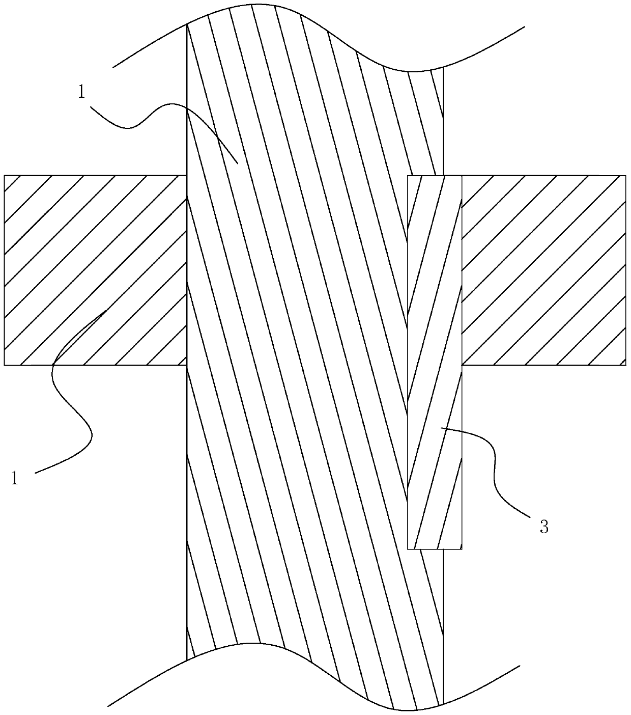
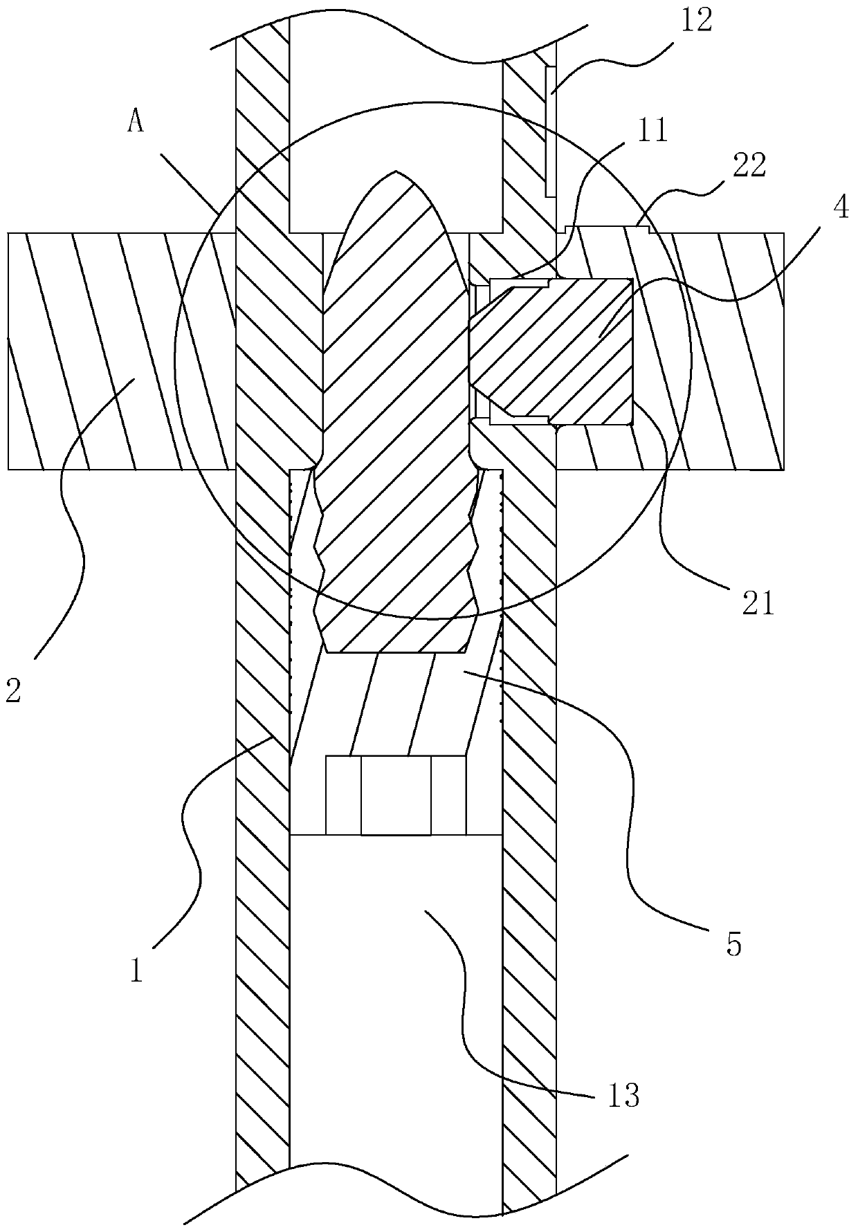
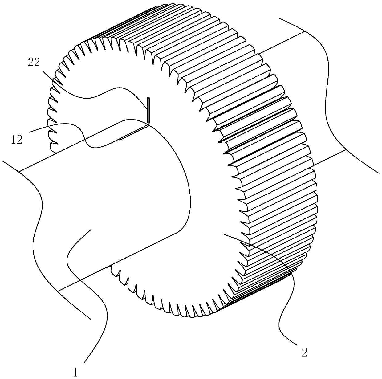
[0037] A gear shaft structure such as figure 2 As shown, it includes a metal round rod shaft 1, a gear 2 sleeved on the metal round rod shaft 1 for the transmission function, set on the metal round rod shaft 1 and capable of clamping with the gear 2 for torque transmission The clamping block 4 and the pressing rod 5 inserted into the metal round rod shaft 1 for pushing the clamping block 4 and the gear 2 to engage; wherein, a metal round rod shaft 1 is provided with a 1 The coaxial line is set for inserting the compression rod 5 into the inner cavity 13 of the metal round rod shaft 1. On the metal round rod shaft 1, there is a pair of two ends connected with the inner cavity 13 and the metal round rod shaft 1 respectively. The outer wall of the gear 2 is communicated with the notch 11 corresponding to the installation position of the gear 2 for the ...


PUM


Abstract

The invention discloses a gear shaft structure, and relates to the technical field of gear shafts. The technical problem that the axial direction of a gear cannot be fixed is solved. According to thetechnical key points, the gear shaft structure comprises a metal round rod shaft and a gear with which the metal round rod shaft is sleeved, the metal round rod shaft is internally provided with an inner cavity arranged on the coaxial line of the metal round rod shaft, the metal round rod shaft is provided with a notch through which the outer wall and the inner cavity of the metal round rod shaftcommunicate, a clamping groove is formed in the inner wall of the gear, a clamping block with the outer wall attached to the inner wall of the notch is arranged in the gap, one end of the clamping block extends out of the metal round rod shaft and is clamped in the clamping groove, and an abutting rod with the outer wall abutting against the surface, close to the axis of the inner cavity, of the clamping block is inserted into the inner cavity. The gear shaft structure has the advantage that the axial direction of the gear can be fixed.

Description

technical field [0001] The invention relates to the technical field of gear shafts, more specifically, it relates to a gear shaft structure. Background technique [0002] A gear shaft refers to a mechanical part that supports a rotating part and rotates with it to transmit motion, torque or bending moment. The gear shaft is generally set as a metal round rod shaft, and a gear is arranged on the metal round rod for transmission. In the prior art , such as gearboxes, planetary gear sets, as well as long optical axes in crane moving mechanisms and drive shafts in automobiles, etc., require a large number of gear shafts. [0003] In the prior art, there are two types of gear shafts, one is the integral type that is integrally formed by using a lathe or casting parts, and the other is the snap-fit ​​type that is formed by snap-fitting of the shaft part and the gear part; among them, the integral type The precision requirements and technical requirements of gear shafts are genera...

Claims


Application Information

Patent Timeline
Patent Type & Authority Patents(China)
IPC IPC(8): F16H57/00F16C3/02F16D1/06
CPCF16H57/0025
Inventor 陈华
Owner 厦门众力达机械有限公司
Why Eureka
Try Eureka