Pipe joint connected with pipe

A pipe connection and pipe joint technology, applied in the direction of pipe/pipe joint/pipe fitting, sealing surface connection, passing element, etc., can solve the problems of seal failure, pipe damage, etc., to reduce damage, leave no gap, and ensure close contact Effect

Pending Publication Date: 2019-07-23
张春燕
View PDF1 Cites 4 Cited by
  • Summary
  • Abstract
  • Description
  • Claims
  • Application Information

AI Technical Summary

Problems solved by technology

[0005] In order to solve the problem that the protruding part of the inner ring of the existing pipe joint is easy to cause damage to the pipe, the outer surface near the thickest part of the protruding part is not in close contact with the inner wall of the pipe and the pipe slides out along the inner ring in a high temperature environment The problem of sealing failure caused, the present invention provides a pipe joint connected with the pipe

Method used


Image

  • Pipe joint connected with pipe
  • Pipe joint connected with pipe
  • Pipe joint connected with pipe

Examples


Embodiment 1

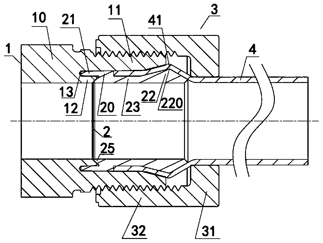
[0041] Such as Figure 3-4 As shown, the fitting includes:

[0042] The joint main body 1 has a coaxially arranged main body cylinder part 10, an outer cylinder part 11 and an inner cylinder part 12. The outer cylinder part 11 and the inner cylinder part 12 protrude in the same direction from the main body cylinder part 10, and the inner cylinder part 12 is arranged In the inner side of the outer tube part 11, the length of the outer tube part 11 protruding from the main body tube part 10 is greater than the length of the inner tube part 12 protruding from the main body tube part 10, and the body tube part 10, the outer tube part 11 and the inner tube part 12 surrounds and forms a groove portion 13, and the opening direction of the groove portion 13 is the same as the protruding direction of the outer cylinder portion 11 and the inner cylinder portion 12.

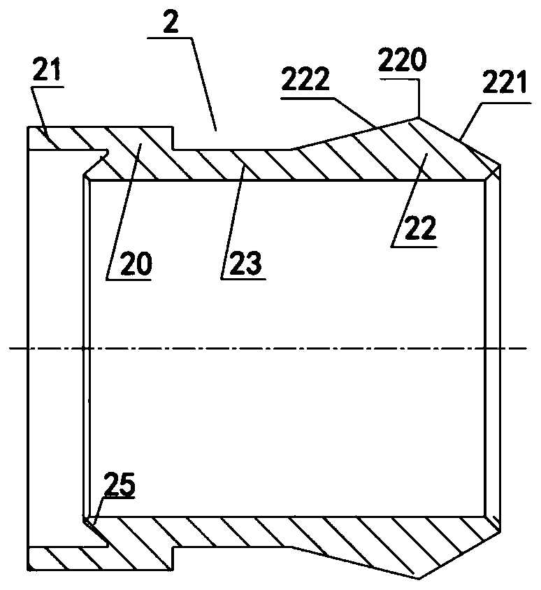
[0043] The inner ring 2 has a cylindrical insertion portion 21, a cylindrical fitting portion 20, a cylindrical connecti...

Embodiment 2

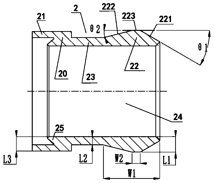
[0070] as attached Figure 6 As shown, in another structure of the inner ring 2, the outer surface of the transition section 223 of the protrusion 22 is a spherical surface, that is, the conical surface 221 with an enlarged diameter and the conical surface 222 with a reduced diameter are connected through the spherical surface transition. The connection is smooth, the spherical surface is in closer contact with the inner wall of the pipe 4, and the sealing effect is better, and the deformation of the pipe 4 is gradual, which can reduce the bending curvature of the pipe 4 and reduce the damage to the pipe 4.

[0071] The included angle θ3 between the tangent at any point on the spherical surface and the axial direction of the inner ring 2 is 0°-35°, and the spherical surface is tangentially connected with the tapered surface 221 with an enlarged diameter and the tapered surface 222 with a reduced diameter at the intersection point. At the point of intersection with the tapered ...


PUM


Abstract

The invention provides a pipe joint connected with a pipe. The pipe joint connected with the pipe comprises a joint body, an inner ring and a screw cap, wherein a transition section is arranged between an expanding conical surface of a projection part of the inner ring and a reducing conical surface of the projection part of the inner ring; the axial length of the transition section is 15 percentto 30 percent of the axial length of the projection part; an included angle between a tangent line at any point on the outer surface of the transition section and the axial direction of the inner ringis 0 degree to 35 degrees; and an included angle between the axial direction of the inner ring and the expanding conical surface is larger than an included angle between the axial direction of the inner ring and the reducing conical surface. The outer surface of the transition section of the projection part and the inner wall of the pipe form surface contact, so that the action area is increased;an extrusion action force between the outer surface of the transition section of the projection part and the inner wall of the pipe is dispersed, and the bending curvature of the pipe is further reduced through the transition section, so that the damage on the pipe is reduced, and the expanding conical surface and the inner wall of the pipe tightly contact and are fastened; and the included anglebetween the axial direction of the inner ring and the expanding conical surface is larger than the included angle between the axial direction of the inner ring and the reducing conical surface, so that the pipe is prevented from outwards slipping off along the reducing conical surface under the high-temperature environment.

Description

technical field [0001] The invention belongs to the technical field of pipe fitting connection, and in particular relates to a pipe joint used in fluid delivery and fluid treatment processes. Background technique [0002] U.S. Patent US5743572A discloses a pipe joint commonly used in the manufacturing process of semiconductor manufacturing, pharmacy, food processing and chemical industry and other technical fields for fluid delivery, as attached figure 1 and 2 As shown, the pipe joint is composed of three parts: a joint body 1 , an inner ring 2 and a nut 3 , and an annular groove 13 is formed between the outer cylinder portion 11 and the inner cylinder portion 12 of the joint body 1 . During use, the front end of the pipe 4 made of resin is sleeved on the outer periphery of the inner ring 2 after flaring, and then inserted into the joint main body 1 together with the inner ring 2, and the pipe 4 is fixed inside the outer cylinder part 11, and the insertion part 21 of the ...

Claims


Application Information

Patent Timeline
Patent Type & Authority Applications(China)
IPC IPC(8): F16L19/02
CPCF16L19/0206
Inventor 贾建东柯文静潘哲
Owner 张春燕
Why Eureka
Try Eureka