Corrugated pipe-based optical fiber stress sensing device

An optical fiber stress and sensing device technology, applied in the field of devices, can solve problems such as hindering the improvement of the dynamic range and accuracy of the optical fiber sensor, limiting the dynamic range and accuracy of the optical fiber sensor, and the size of the plate cannot be too large, so as to achieve flexible use methods. , Increase the detection accuracy and sensitivity, increase the effect of the effective bending length

Inactive Publication Date: 2012-02-01
XIAN JINHE OPTICAL TECH
View PDF1 Cites 2 Cited by
  • Summary
  • Abstract
  • Description
  • Claims
  • Application Information

AI Technical Summary

Problems solved by technology

However, the fiber grating type sensor also has disadvantages: 1) the dynamic range is small, the fiber grating is generally made of bare optical fiber exposed to ultraviolet rays, its intensity value is low, and the deformation ability is small, resulting in a small dynamic range; in addition, a good Encapsulation can only be used, and encapsulation is a process with high cost; 2) The cost of test equipment is high, and it needs to be used with high-priced optical wavelength demodulation equipment
[0008] The solution provided by Chinese patent 87107210 is based on the microbending loss of the optical fiber to realize the microbending optical fiber strain gauge, but because it i

Method used


Image

  • Corrugated pipe-based optical fiber stress sensing device
  • Corrugated pipe-based optical fiber stress sensing device
  • Corrugated pipe-based optical fiber stress sensing device

Examples


Example Embodiment

[0037] Example 1

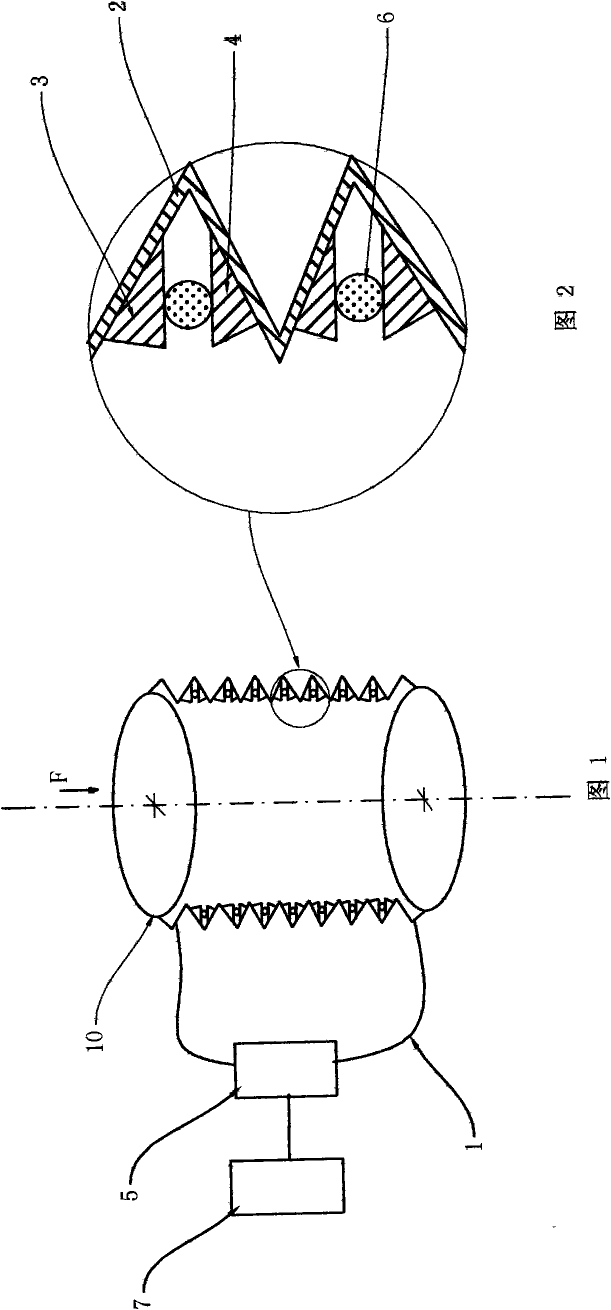
[0038] like figure 1 , figure 2 As shown, the present invention includes a side A deforming tooth 3 and a side B deforming tooth 4 respectively arranged on two opposite surfaces of the concave part of the inner wall of the pipe wall 2 of the bellows 10, and the deforming tooth 3 on the A side and the deforming tooth on the B side are respectively arranged. The teeth 4 are staggered and correspond to each other. The deformed teeth 3 on the A side and the deformed teeth 3 on the B side are correspondingly arranged on both sides of the signal fiber 6. The signal fiber 6 is connected to the test unit 5 through the extension fiber 1, and the test unit 5 is followed by a processing unit 7.

[0039] When the bellows 10 is stretched and deformed under stress, the distance between the deformed teeth 3 on the A side and the deformed teeth 4 on the B side on the wall 2 of the bellows 10 will also change, so that the deformed teeth are clamped between the two deformed...

Example Embodiment

[0044] Example 2

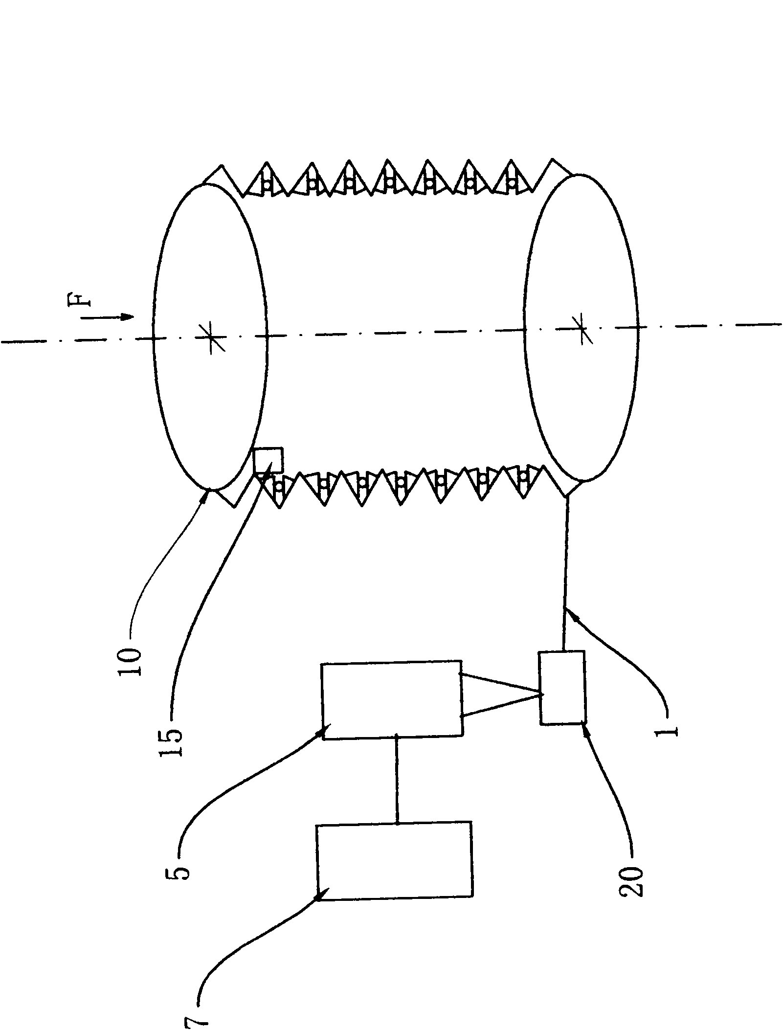
[0045] like image 3 As shown, in this embodiment, the difference from Embodiment 1 is that a light reflector 15 is arranged at one end of the signal fiber 6, the other end of the signal fiber 6 is connected to the extension fiber 1, and the extension fiber 1 is connected to a 1X2 optical branch. The 2 ends of the 1X2 optical splitter 20 are connected to the test unit 5, the test unit 5 can be composed of a stable light source and an optical power meter, and the test unit 5 is connected with the processing unit 7, so that the optical signal transmitted in the signal fiber 6 can be Passing through the bent portion of the signal fiber 6 twice further improves the precision and sensitivity of the detection device. In this embodiment, the structures, connection relationships and working principles of other parts are the same as those in Embodiment 1.

Example Embodiment

[0046] Example 3

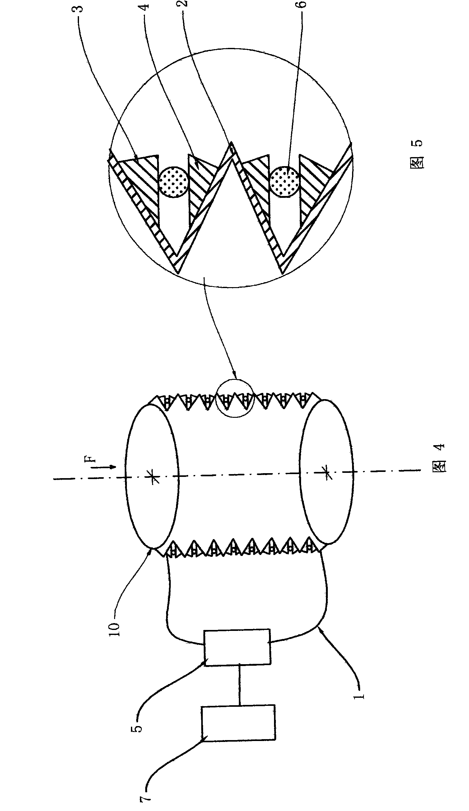
[0047] like Figure 4 , Figure 5 As shown, in this embodiment, the difference from Embodiment 1 is that the A-side deforming teeth 3 and the B-side deforming teeth 4 are arranged in the concave part of the outer wall of the pipe wall 2 of the corrugated pipe 10 . In this embodiment, the structures, connection relationships and working principles of other parts are the same as those in Embodiment 1.


PUM


Abstract

The invention discloses a corrugated pipe-based optical fiber stress sensing device. An A-side deformation tooth and a B-side deformation tooth which correspond to each other in a staggering manner are respectively arranged on two opposite surfaces at the sunk place of a corrugated pipe wall, and a signal optical fiber is clamped between two deformation teeth. When a corrugated pipe expands and deforms under stress, a distance between the A-side deformation tooth and the B-side deformation tooth on the corrugated pipe wall changes, so that a bending curvature of the signal optical fiber clamped between the two deformation teeth changes, and bending loss of the signal optical fiber changes, the change degree of the bending loss of the signal optical fiber can be obtained through a test unit, and the stress size of the corrugated pipe can be calculated. The corrugated pipe and an optical fiber micro-bending structure are organically combined to form an intelligent device with many advantages of high precision, soundness and durability, strong adaptability and convenience and flexibility for use. The corrugated pipe-based optical fiber stress sensing device has broad application prospect.

Description

technical field [0001] The invention belongs to an optical fiber stress sensing device, in particular to a device based on a corrugated tube and achieves the purpose of stress sensing by detecting the change of optical fiber microbending loss. Background technique [0002] The bellows has a wide range of uses. The bellows is an elastic element that can be deformed longitudinally and is basically not deformed laterally. In terms of sensing, it can be used for various measurement, adjustment, control, and sensing instruments. And seals, etc.; as the flexible section of the expansion joint, it can be used to compensate for the axial, lateral and angular displacement of the pipeline due to temperature difference, and can also be used in the pipeline to compensate for positional deviation, absorb the vibration of the pipeline, etc. It can be seen that the bellows, as a key element in the sensing device, can be adapted to a variety of practical application environments. [0003] ...

Claims


Application Information

Patent Timeline
IPC IPC(8): G01L1/24
Inventor 杜兵
Owner XIAN JINHE OPTICAL TECH
Why Eureka
Try Eureka