Universal pressure sensing device based on optical fiber microbending loss

A sensing device, a general-purpose technology, applied in fluid pressure measurement using optical methods, measurement of force by measuring the change of optical properties of materials when they are stressed, etc. The practicality and promotion of sensors, the limitation of practical application and application scope, etc., achieve the effect of flexible use, simple structure, and extended effective length

Inactive Publication Date: 2012-03-14
XIAN JINHE OPTICAL TECH
View PDF1 Cites 8 Cited by
  • Summary
  • Abstract
  • Description
  • Claims
  • Application Information

AI Technical Summary

Problems solved by technology

The main defect of the former is that the optical fiber is discontinuous in the sensing device, and there is a problem of end surface pollution, which affects the long-term use accuracy of the optical fiber sensing device. Loss type device, two sawtooth plates that have been strictly processed are placed in parallel, and the optical fiber is clamped between the two parallel sawtooth plates. The deformation of the optical fiber in this device is very small, only a few hundred microns, resulting in a small detection range, which limits its practicality. and scope of application; another type is Chinese patent 93206204.0 "optical fiber sensing pressure head", and the article "optical fiber based on C-type spring tube and optical fiber ring" in Journal of Xi'an University of Technology (2000) Vol.16No.1p.69-73 Proposed in "Pressure Sensor": The optical fiber disk is made into an optical fiber ring with a diameter of about 5-10mm, and placed between the fixed bracket and the C-shaped spring tube through the clamp. When there is a pressure change, the position of the C-shaped spring tube is relatively Due to the change of the fixed bracket, the bending curvature of the fiber ring is changed, resulting in the change of the bending loss of the optical signal transmitted by the optical fiber in the fiber ring. By detecting the change of the bending loss, the change of the monitoring pressure can be obtained, but in the two devices The optical fiber ring requires a diameter of about 5-10mm, and most optical fibers will have a large bending internal stress under this bending curvature, and the optical fiber will break in a short time, resulting in the failure of the optical fiber sensor. The practicality and popularization of this kind of sensor

Method used


Image

  • Universal pressure sensing device based on optical fiber microbending loss
  • Universal pressure sensing device based on optical fiber microbending loss
  • Universal pressure sensing device based on optical fiber microbending loss

Examples


Embodiment 1

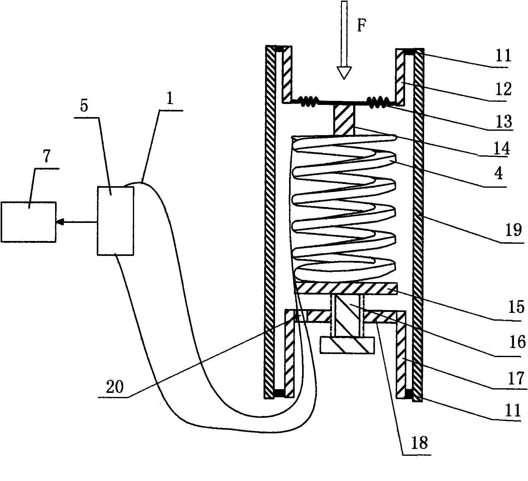
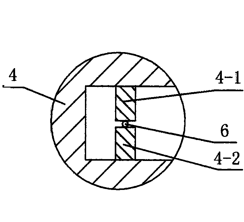
[0035] like figure 1 , figure 2 As shown, the present invention has a multi-layer microbending element composed of a curved housing 4 that includes a signal optical fiber 6, and the lower deforming teeth 4-1 and the upper deforming teeth 4-1 fixed in the curved housing 4 2. Corresponding to each other and clamping the signal fiber 6 between the two, the signal fiber 6 is connected to the test unit 5 through the extension fiber 1, and the test unit 5 is connected with the processing unit 7, and there are two layers of cavities outside the curved housing 4 , the upper edge and the lower edge of the inner wall of the cylindrical cavity 19 are respectively fixed with an inner cylindrical cavity A12 and an inner cylindrical cavity B17, and the lower end of the inner cylindrical cavity A12 is provided with a corrugated sheet 13, and the inner cylindrical cavity The upper end of the body B17 is provided with a base plate 18 . The corrugated sheet 13 transmits the received pressure...

Embodiment 2

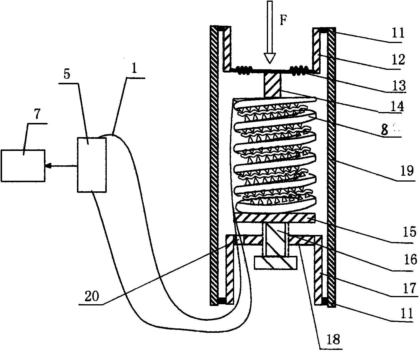
[0039] like image 3 , Figure 4 As shown, in this embodiment, the difference from Embodiment 1 is that the multi-turn micro-bending element is composed of a spring-shaped element with two adjacent coils of spring wire 8 that are interlaced with corresponding deformation teeth. A signal optical fiber 6 is clamped. In this embodiment, the structures, connections and working principles of other parts are the same as those in Embodiment 1.

Embodiment 3

[0041] like Figure 5 As shown, in this embodiment, the difference from Embodiment 1 is that an optical reflector 22 is arranged at one end of the signal fiber 6, the other end of the signal fiber 6 is connected to the extension fiber 1, and the extension fiber 1 is connected to a 1X2 optical branch Device 21, 2 terminals of 1X2 optical splitter 21 are connected to test unit 5, and this test unit 5 is made of stable light source and optical power meter, that is to say, 2 ends of 1X2 optical splitter 21 are respectively connected with stable light source and optical power meter, The testing unit 5 is connected with the processing unit 7, so that the optical signal transmitted in the signal fiber 6 can pass through the bending part of the signal fiber 6 twice, which further improves the accuracy and sensitivity of the detection device. In this embodiment, the structures, connections and working principles of other parts are the same as those in Embodiment 1.


PUM

PropertyMeasurementUnit
diameteraaaaaaaaaa

Abstract

The invention discloses a universal pressure sensing device based on an optical fiber microbending loss, which comprises a cylindrical cavity, wherein one end of the cylindrical cavity is closed by a substrate, and the other end of the cylindrical cavity is fixedly provided with a corrugated piece; and a multi-layer microbending element containing a signal optical fiber is fixedly arranged between the substrate and the corrugated piece. When the tested pressure acts on the corrugated piece, the corrugated piece deforms and transfers the force to the multi-layer microbending element to allow the multi-layer microbending element to be compressed, so that the bending curvature of the signal optical fiber contained in the multi-layer slightly bent element changes, and thus the power of optical signals transmitted in the signal optical fiber is obviously changed, and the pressure is tested by the detection of a testing unit. The multi-layer microbending loss element is adopted, so that the effective length of the signal optical fiber is lengthened, the bending curvature of the signal optical fiber is reduced, and thus the precision of the device is improved, the service life of the signal optical fiber is substantially prolonged simultaneously, and the device has broad application prospects.

Description

technical field [0001] The invention relates to a pressure sensing device, in particular to a universal pressure sensing device based on multilayer optical fiber microbend loss. Background technique [0002] There are many types of optical fiber pressure sensing devices, mainly including light intensity modulation optical fiber sensing devices, fiber grating pressure sensing devices, optical fiber interference pressure sensing devices, etc. The latter two are characterized by sensing sensitivity However, in the actual application process, there are defects and deficiencies such as complex equipment and high operating costs, which greatly restrict the application and promotion of optical fiber sensing devices. In the optical intensity modulation optical fiber pressure sensing device, there are mainly membrane reflection type or microbending loss type structure. The main defect of the former is that the optical fiber is discontinuous in the sensing device, and there is a prob...

Claims


Application Information

Patent Timeline
Patent Type & Authority Applications(China)
IPC IPC(8): G01L1/24G01L11/02
Inventor 杜兵
Owner XIAN JINHE OPTICAL TECH
Why Eureka
Try Eureka