Balloon catheter
A technology of balloon catheters and balloons, which is applied in the direction of balloon catheters, catheters, surgery, etc., can solve the problems that the balloon catheter cannot be pushed further, and the wire cannot be smooth, so as to reduce the possibility and improve the operability
- Summary
- Abstract
- Description
- Claims
- Application Information
AI Technical Summary
Problems solved by technology
Method used
Image
Examples
Embodiment 1
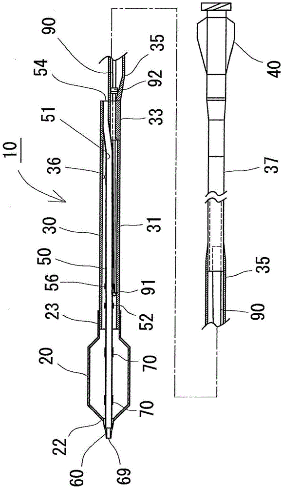
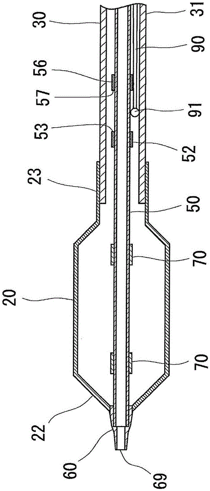
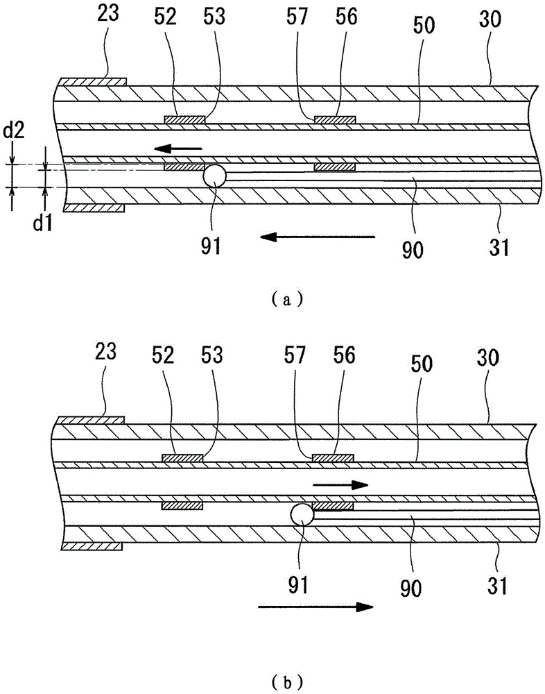
[0034] Such as figure 1 As shown, for example, a balloon catheter 10 used for treating a stenosis in a blood vessel of the heart includes a balloon 20 , an outer shaft 30 , a coupling tube 40 , an inner shaft 50 , a flap 60 , and a core wire 90 as a reinforcement.
[0035] The balloon 20 has a function of expanding a narrow portion and is made of a resin member. Furthermore, it has a front end mounting part 22 on the front end side, and has a rear end mounting part 23 on the rear end side. The front end mounting portion 22 is joined to the front end of the inner shaft 50 via the sheet 60 , and the rear end mounting portion 23 is joined to the front end of the outer shaft 30 .
[0036] The outer shaft 30 has a function of supplying fluid, and is composed of a tubular member constituting an expansion lumen 36 for supplying the fluid. Further, the outer shaft 30 has a front end outer shaft portion 31 , a wire port portion 33 , an intermediate outer shaft portion 35 , and a rear...
Embodiment 2
[0053] according to Figure 4 (a) The balloon catheter 12 of the second embodiment will be described. In addition, the same structure as Example 1 is attached|subjected with the same code|symbol, and description is abbreviate|omitted.
[0054] Such as Figure 4 As shown in (a), the inner shaft 250 has a rear end side shaft portion 252 and a front end side shaft portion 251 joined to the front end of the rear end side shaft portion 252 . In addition, it is preferable that the said rear-end side shaft part 252 and the said front-end side shaft part 251 are comprised by the cylindrical body whose inner diameter and outer diameter are substantially equal to each other.
[0055] In addition, the front end side shaft portion 251 is formed of a resin that is softer than the resin forming the rear end side shaft portion 252 .
[0056] Also, the front end of the rear shaft portion 252 is inserted into the rear end of the front shaft portion 251 , and the rear end of the front shaft ...
Embodiment 3
[0061] according to Figure 4 (b) The balloon catheter 13 of the third embodiment will be described. In addition, the same code|symbol is attached|subjected to the same structure as Example 1, 2, and description is abbreviate|omitted suitably.
[0062] Such as Figure 4 As shown in (b), the inner shaft 350 has a rear end side shaft portion 352 and a front end side shaft portion 351 joined to the front end of the rear end side shaft portion 352 . In addition, it is preferable that the said rear-end side shaft part 352 and the said front-end side shaft part 351 are comprised by the cylindrical body whose inner diameter and outer diameter are substantially equal to each other.
[0063] In addition, the front end side shaft portion 351 is made of a resin that is softer than the resin forming the rear end side shaft portion 352 .
[0064] In addition, the rear end of the front end side shaft portion 351 is inserted into the front end of the rear end side shaft portion 352 , and ...
PUM
 Abstract
Description
Claims
Application Information
 - R&D
- Intellectual Property
- Life Sciences
- Materials
- Tech Scout
- Unparalleled Data Quality
- Higher Quality Content
- 60% Fewer Hallucinations
Browse by: Latest US Patents, China's latest patents, Technical Efficacy Thesaurus, Application Domain, Technology Topic, Popular Technical Reports.
© 2025 PatSnap. All rights reserved.Legal|Privacy policy|Modern Slavery Act Transparency Statement|Sitemap|About US| Contact US: help@patsnap.com


