Optical fiber type non-invasive pipeline pressure sensor

A non-invasive, pipeline pressure technology, applied in fluid pressure measurement using optical methods, force measurement by measuring the change of optical properties of materials when they are stressed, etc. High, difficult to use and other problems, to achieve the effect of flexible use, convenient processing and long service life

Inactive Publication Date: 2010-12-01
XIAN JINHE OPTICAL TECH
View PDF1 Cites 8 Cited by
  • Summary
  • Abstract
  • Description
  • Claims
  • Application Information

AI Technical Summary

Problems solved by technology

However, the implementation of the scheme proposed by this invention has the problems of high cost and difficulty in use. This scheme needs to measure the length change of the optical fiber wound on the surface of the pipe, which requires the use of high-cost interferometric instruments to accurately test; in addition, for Bragg gratings The test of the reflection wavelength change also requires precision equipment such as a high-precision spectrometer
High cost limits the application scope of the optical fiber sensing device of this scheme

Method used


Image

  • Optical fiber type non-invasive pipeline pressure sensor
  • Optical fiber type non-invasive pipeline pressure sensor
  • Optical fiber type non-invasive pipeline pressure sensor

Examples


Embodiment 1

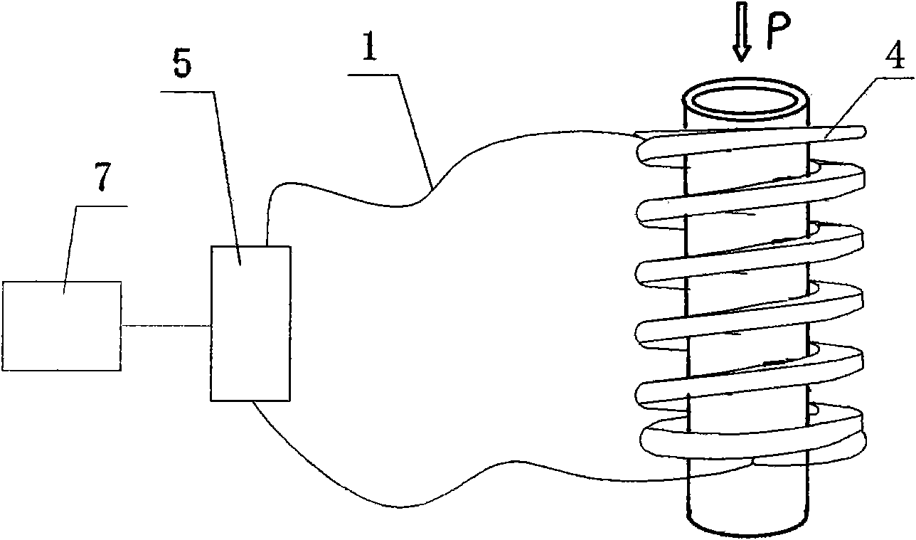
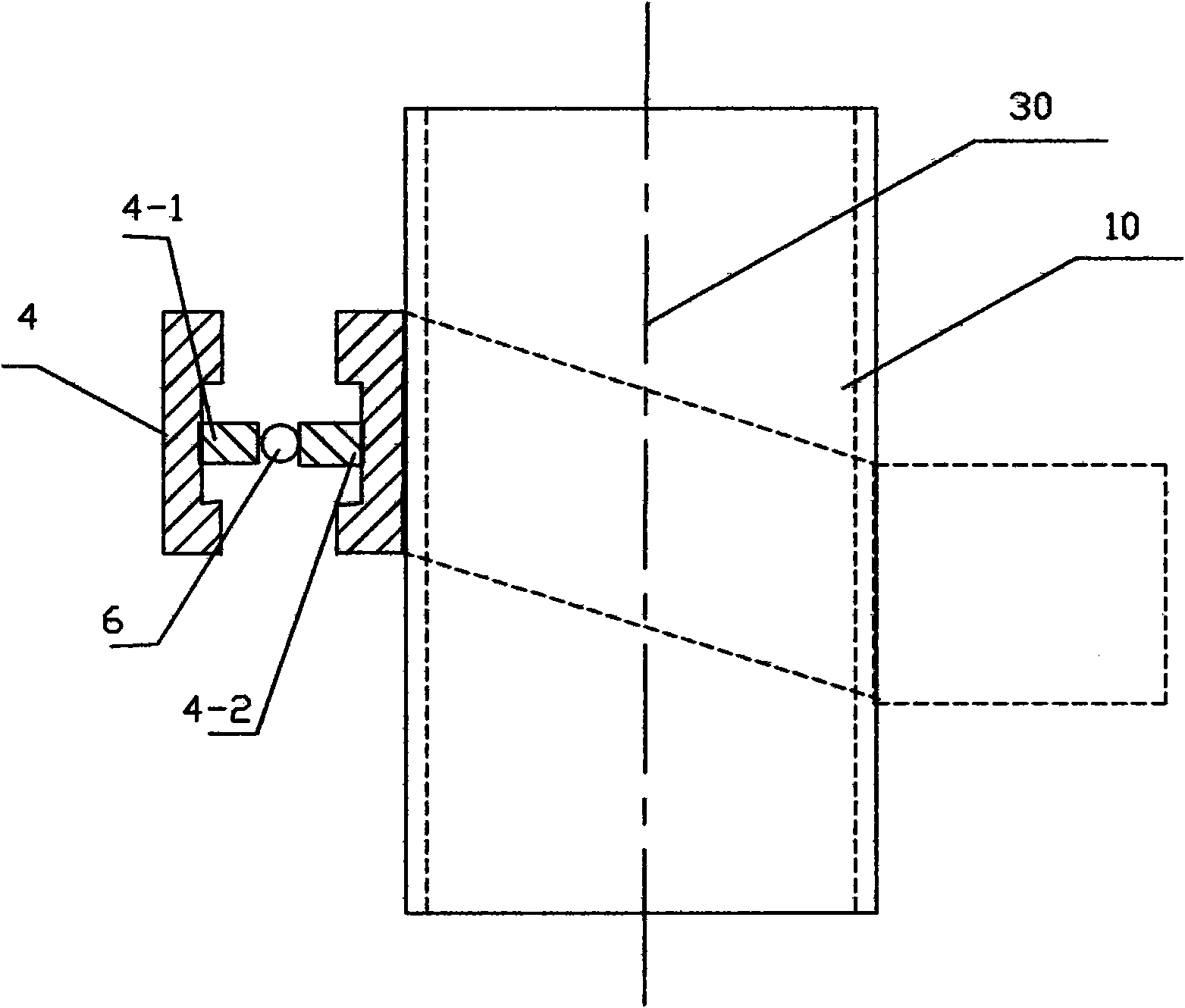
[0029] Such as figure 1 , figure 2 As shown, in the present invention, the curved casing 4 wound on the pipeline 10 to be tested is arranged on a plurality of A-side deformation teeth 4-1 and a plurality of B-side deformation teeth 4-1 on opposite sides of the curved casing 4. The deformed teeth 4-2, the A-side deformed teeth 4-1 and the B-side deformed teeth 4-2 are arranged in a staggered manner, and the A-side deformed teeth 4-1 and the B-side deformed teeth 4-2 are correspondingly arranged on the signal optical fiber 6 On both sides, the extension optical fiber 1 of the signal optical fiber 6 is connected to the test unit 5 , and the processing unit 7 is connected behind the test unit 5 .

[0030] When the internal pressure of the pipeline 10 increases or decreases, the circumference of the pipeline 10 will increase or decrease, so that the distance between the deformed teeth on the opposite sides of the curved shell 4 wound on the pipeline 10 will change, which will als...

Embodiment 2

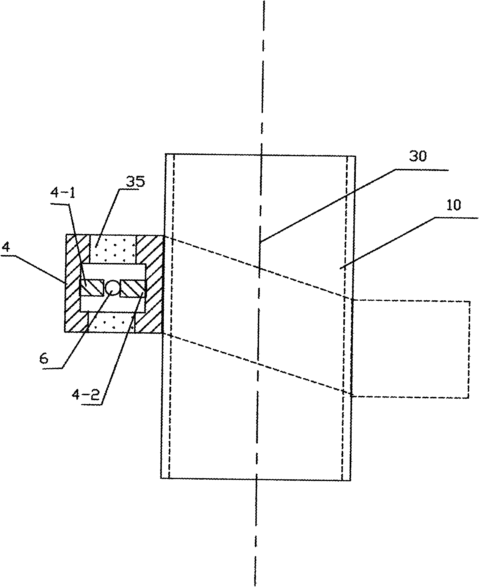
[0035] Such as image 3 As shown, in this embodiment, the difference from Embodiment 1 is that the two sides A and B inside the curved housing 4 are connected by an elastic material 35 . This can improve the accuracy and stability of the curved housing. In this embodiment, the structures, connections and working principles of other parts are the same as those in Embodiment 1.


PUM


Abstract

The invention discloses an optical fiber type non-invasive pipeline pressure sensor, which comprises a curve type shell wound on the pipeline to be tested, a plurality of A-side deformation teeth and a plurality of B-side deformation teeth, wherein the A-side deformation teeth and B-side deformation teeth are distributed on opposite two sides in the curve type shell in staggered arrangement and are arranged on both sides of a signal optical fiber correspondingly. The prolonged optical fiber of the signal optical fiber is connected with a test unit. When the inner pressure of the pipeline increases or decreases, the circumference of the pipeline is to increase or decrease so that the distance between the deformation teeth on opposite sides within the curve type shell winding on the pipeline is to change, thereby changing the curvature of the signal optical fiber clamped between the deformation teeth on opposite sides. The test unit acquires the change of the inner pressure of the pipeline by detecting the change of the inner transmission optical signal power of the signal optical fiber. The device has the advantages of high precision, low failure rate and wide application prospect.

Description

technical field [0001] The invention relates to the detection of the pressure around the pipeline, more specifically, it relates to a non-invasive optical fiber pressure sensing device for measuring the pressure in the pipeline. Background technique [0002] In the oil and gas industry, it has been known that measuring the pressure of liquids and gases in pipelines is very useful for the detection and production of oil and gas. However, typical pressure sensors require drilling a hole in the pipe wall to transmit the pressure to the sensor, or placing the sensor or part of the sensor in the pipe. Drilling holes in the pipe is costly and adds to the system's potential for failure. Therefore, there is a need to measure the pressure in the pipeline in a non-invasive manner. [0003] Chinese Patent Application No. 99807831.X "Non-Insert Fiber Optic Pressure Sensor for Measuring Unstable Pressure in Pipelines" proposes a device in which optical fibers are wound into coils aroun...

Claims


Application Information

Patent Timeline
Patent Type & Authority Applications(China)
IPC IPC(8): G01L1/24G01L11/02
Inventor 杜兵杜蔚杜迎涛
Owner XIAN JINHE OPTICAL TECH
Why Eureka
Try Eureka