Optical fiber sensing device based on functional material

A functional material, optical fiber sensing technology, applied in the direction of using optical devices to transmit sensing components, etc., can solve the problems of limiting the service life and use range of optical fiber sensing devices, difficult and greatly extending the effective bending length of optical fibers, etc. Flexible use, extending effective length, reducing the effect of bending curvature

Inactive Publication Date: 2012-03-14
XIAN JINHE OPTICAL TECH
View PDF0 Cites 5 Cited by
  • Summary
  • Abstract
  • Description
  • Claims
  • Application Information

AI Technical Summary

Problems solved by technology

[0006] The existing microbending optical fiber sensing device is a sawtooth plate periodic microbending loss type device. The typical structure is that two strictly processed sawtooth plates are placed in parallel, and the optical fiber is clamped between the two parallel sawtooth plates. The optical fiber in the device The amount of deformation is very small, only a few hundred microns, resulting in a small detection range, and it is difficult to effectively control the minimum bending curvature of the optical fiber. In addition, the effective bending length of the optical fiber is not easy to be greatly extended, which limits the service life of this type of optical fiber sensing device and scope of use

Method used


Image

  • Optical fiber sensing device based on functional material
  • Optical fiber sensing device based on functional material
  • Optical fiber sensing device based on functional material

Examples


Embodiment 1

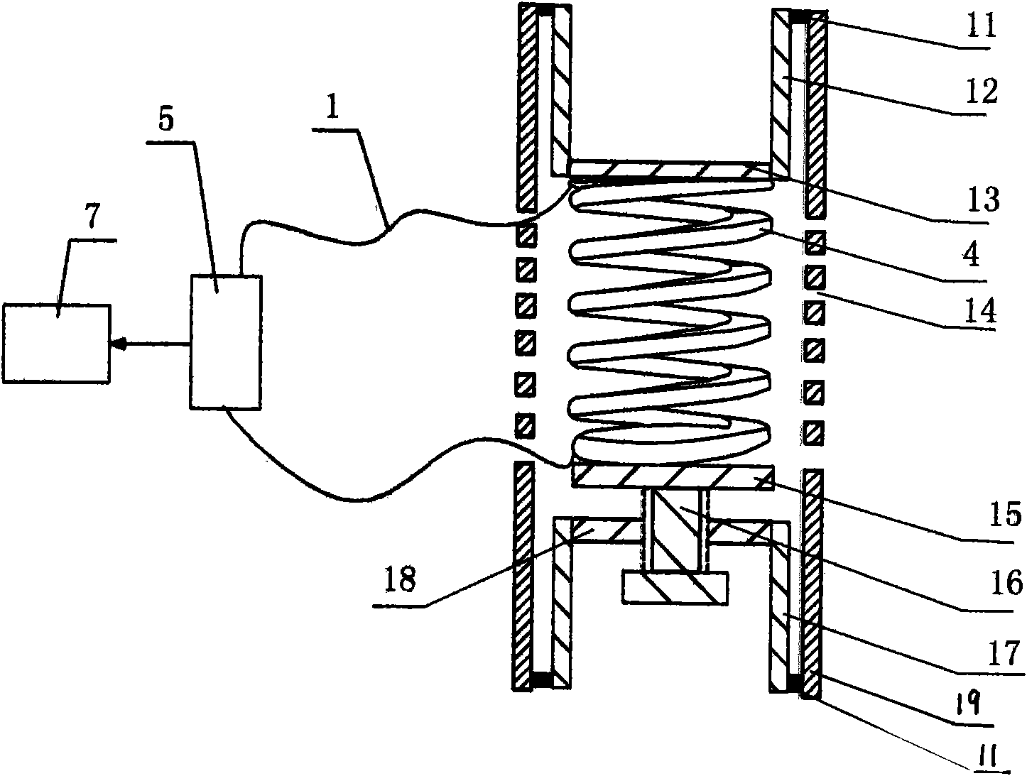
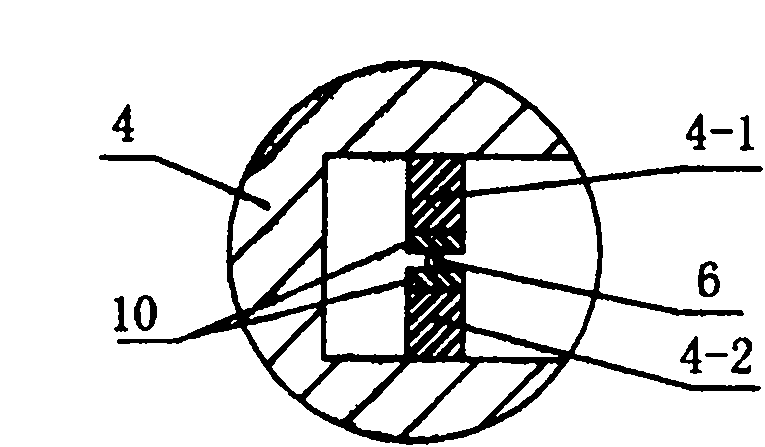
[0042] like figure 1 , figure 2 As shown, the present invention has a multi-turn microbending element composed of a curved housing 4 that includes a signal optical fiber 6, and the lower deforming teeth 4-1 and the upper deforming teeth 4-1 fixed in the curved housing 4 2. The surface is covered with functional materials 10. The signal optical fiber 6 is connected to the test unit 5 through the extension optical fiber 1. The test unit 5 is followed by a processing unit 7. There are two layers of shells outside the curved shell 4. The inner shell is made of no The interconnected upper inner layer shell 12 and the lower inner layer shell 17 are composed of two shells. The inner and outer shells are respectively fixed together at the two ends of the outer shell 19 through fixed points 11. One end of the curved shell 4 It is connected with the base plate 13 of the upper inner shell 12, the other end of the curved shell 4 is connected with the base plate 15, the base plate 15 is ...

Embodiment 2

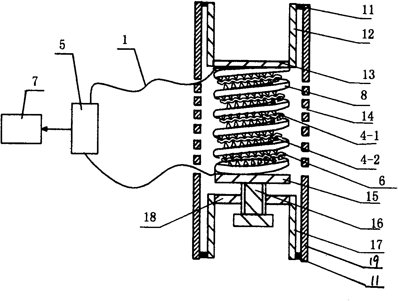
[0049] like image 3 , Figure 4 As shown, in this embodiment, the difference from Embodiment 1 is that the multi-turn micro-bending element is composed of a spring-shaped element with two adjacent coils of spring wire 8 that are interlaced with corresponding deformation teeth. A signal optical fiber 6 is clamped. In this embodiment, the structures, connections and working principles of other parts are the same as those in Embodiment 1.

Embodiment 3

[0051] like Figure 5 , Image 6 As shown, in this embodiment, the difference from Embodiment 1 is that the multi-turn microbending element is composed of a bellows 25, and no double-layer bridge temperature compensation housing is installed outside the bellows 25, and the bellows 25 wall 2 Deformation teeth corresponding to each other are respectively arranged on the opposite two surfaces of the lower recess, and the signal optical fiber 6 is clamped between the deformation teeth. Wherein the lower deformation teeth 4-1 and the upper deformation teeth 4-2, or the pipe wall 2 of the bellows 25 are made of functional materials 10 . In this embodiment, the structures, connections and working principles of other parts are the same as those in Embodiment 1.


PUM


Abstract

The invention discloses an optical fiber sensing device based on a functional material, which comprises a multi-ring slightly bent element for clamping a signal optical fiber, wherein at least one part of the multi-ring slightly bent element is made by the functional material, i.e., all or part of deformed teeth, or all or part of regions in which the deformed teeth are fixed is made by the functional material, and the functional material varies with the change of physical quantities to be tested. The distance between the deformed teeth in the multi-ring slightly bent element is changed when the physical quantities to be tested change, so that the bending curvature of the signal optical fiber clamped between the deformed teeth is changed, and thus the power of an optical signal transmitted in the signal optical fiber is obviously changed, and the change size of the physical quantities to be tested is tested by the detection of a testing unit. The multi-ring slightly bent element is adopted, so that the effective length of the signal optical fiber is lengthened, the bending curvature of the signal optical fiber is reduced, and thus the precision is improved, the service life is prolonged, and the device has broad application prospects.

Description

technical field [0001] The invention belongs to the field of optical fiber sensing, and in particular relates to an optical fiber sensing device composed of a microbending structure with functional material properties and based on the change of optical fiber microbending loss. Background technique [0002] The optical fiber microbend sensor is a light intensity modulated sensor, which has the characteristics of low cost, high sensitivity, and certain environmental anti-interference ability. Its implementation is based on the bending or microbending loss of the optical fiber. By changing the bending degree of the optical fiber, the output optical power changes. [0003] The principle of optical power loss in fiber optic microbending sensors is: when the optical fiber is disturbed by bending, bending loss will occur, mainly microbending loss and macrobending loss, and there is no strict distinction between the two losses. Both bending losses are caused by the coupling of part...

Claims


Application Information

Patent Timeline
Patent Type & Authority Applications(China)
IPC IPC(8): G01D5/26
Inventor 杜兵
Owner XIAN JINHE OPTICAL TECH
Why Eureka
Try Eureka