Fiber pressure sensing device based on C-shaped spring tube

The technology of a sensing device and a spring tube, applied in the field of devices, can solve the problems affecting the long-term use accuracy of the optical fiber sensing device, limiting the practicality and promotion of the sensor, limiting the practical application and the application range, etc., and achieves flexible use mode and simple structure. , the effect of extending the effective length

Inactive Publication Date: 2010-12-22
XIAN JINHE OPTICAL TECH
View PDF1 Cites 11 Cited by
  • Summary
  • Abstract
  • Description
  • Claims
  • Application Information

AI Technical Summary

Problems solved by technology

The main defect of the former is that the optical fiber is discontinuous in the sensing device, and there is a problem of end surface pollution, which affects the long-term use accuracy of the optical fiber sensing device. Loss type device, two sawtooth plates that have been strictly processed are placed in parallel, and the optical fiber is clamped between the two parallel sawtooth plates. The deformation of the optical fiber in this device is very small, only a few hundred microns, resulting in a small detection range, which limits its practicality. and scope of application; another type is Chinese patent 93206204.0 "optical fiber sensing pressure head", and the article "optical fiber based on C-type spring tube and optical fiber ring" in Journal of Xi'an University of Technology (2000) Vol.16No.1p.69-73 Proposed in "Pressure Sensor": The optical fiber disk is made into an optical fiber ring with a diameter of about 5-10mm, and placed between the fixed bracket and the C-shaped spring tube through the clamp. When there is a pressure change, the position of the C-shaped spring tube is relatively Due to the change of the fixed bracket, the bending curvature of the fiber ring is changed, resulting in the change of the bending loss of the optical signal transmitted by the optical fiber in the fiber ring. By detecting the change of the bending loss, the change of the monitoring pressure can be obtained, but in the two devices The optical fiber ring requires a diameter of about 5-10mm, and most optical fibers will have a large bending internal stress under this bending curvature, and the optical fiber will break in a short time, resulting in the failure of the optical fiber sensor. The practicality and popularization of this kind of sensor

Method used


Image

  • Fiber pressure sensing device based on C-shaped spring tube
  • Fiber pressure sensing device based on C-shaped spring tube
  • Fiber pressure sensing device based on C-shaped spring tube

Examples


Embodiment 1

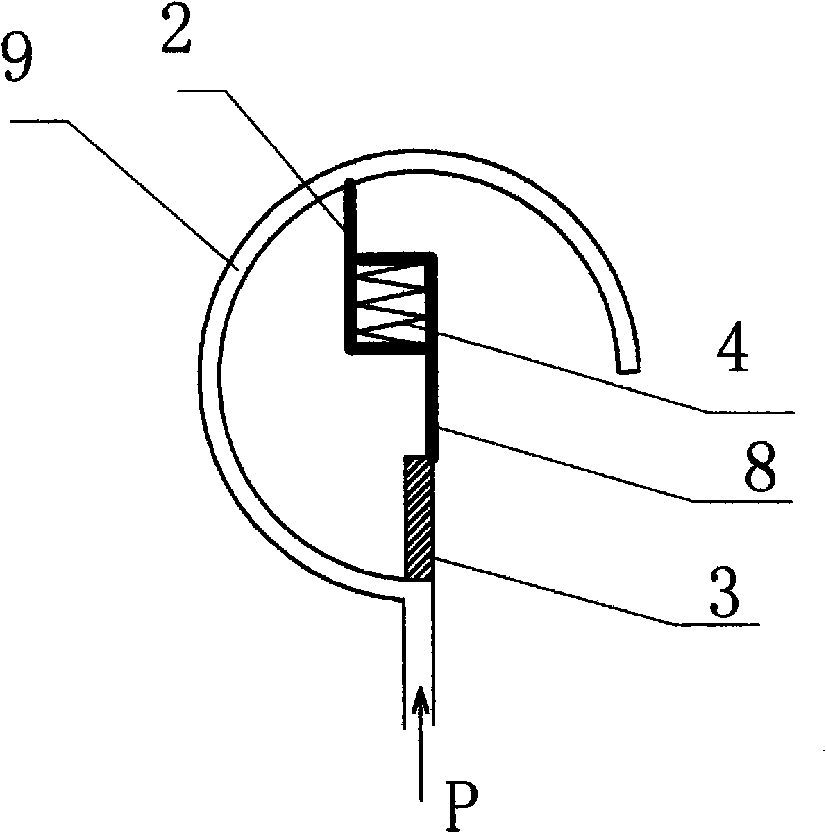
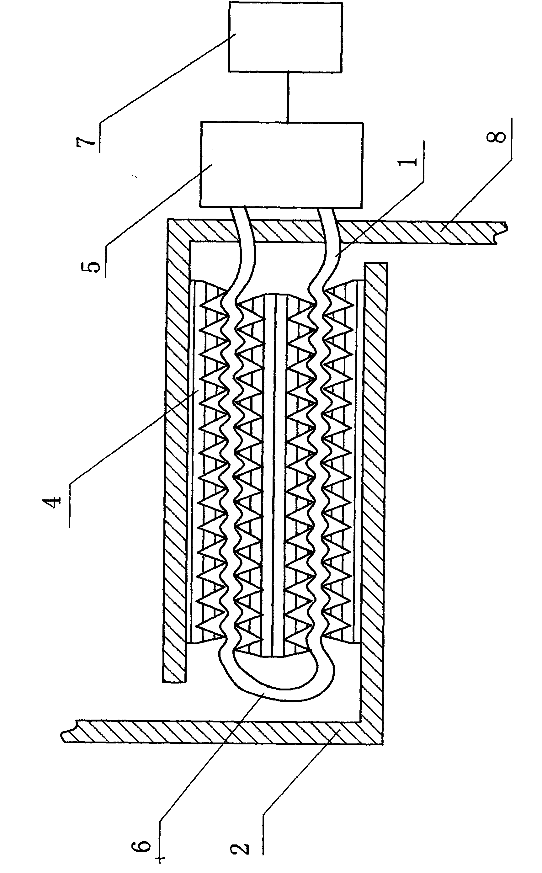
[0029] Such as figure 1 , figure 2 As shown, in the present invention, two ends of a multi-layer microbending element 4 including a signal optical fiber 6 are respectively installed on a C-shaped spring tube 9 and a fixing bracket 3 through a clamp 2 and a clamp 8 . The signal optical fiber 6 is connected to the test unit 5 through the extension optical fiber 1, and the processing unit 7 is connected behind the test unit 5. The change of the bending curvature of the signal optical fiber 6 will cause the change of the optical signal transmitted inside the signal optical fiber 6. After passing through the test unit 5 The change of the optical signal can be monitored and processed by the processing unit 7 . When the measured pressure P passes into the C-shaped spring tube 9, the C-shaped spring tube 9 tends to become round and straighten, and the straightening displacement of the C-shaped spring tube 9 drives the clamp 2, so that the position between the clamp 2 and the clamp 8...

Embodiment 2

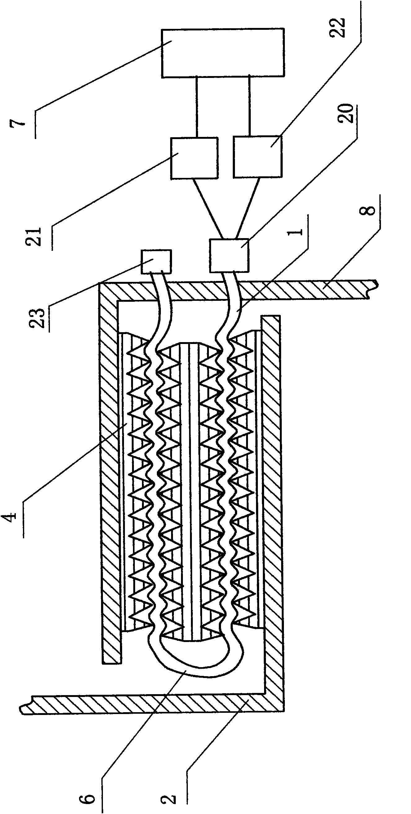
[0034] Such as image 3 As shown, in this embodiment, the difference from Embodiment 1 is: a light reflector 23 is arranged at one end of the signal fiber 6, the other end of the signal fiber 6 is connected to the extension fiber 1, and the extension fiber 1 is connected to a 1X2 optical branch Device 20, 2 ends of 1X2 optical splitter 20 are respectively connected with stable light source 21 and photodetector 22, and stable light source 21 and photodetector 22 are connected with processing unit 7 again, can make the optical signal transmitted in signal optical fiber 6 pass through twice like this The bent portion of the signal optical fiber 6 further improves the accuracy and sensitivity of the detection device. In this embodiment, the structures, connections and working principles of other parts are the same as those in Embodiment 1.

Embodiment 3

[0036] Such as Figure 4 As shown, in this embodiment, the difference from Embodiment 1 is that the multi-layer microbending element 4 is composed of a helical microbending element with two rows of deformed teeth corresponding to each other, and the gap between the two rows of deformed teeth is A signal optical fiber 6 is clamped. In this embodiment, the structures, connections and working principles of other parts are the same as those in Embodiment 1.


PUM


Abstract

The invention discloses a fiber pressure sensing device based on a C-shaped spring tube. A multi-layer microbend element containing a signal fiber is installed on the C-shaped spring tube. When the pressure to be measured is applied to the C-shaped spring tube, the C-shaped spring tube has the tendency of rounding and extending, and the extending displacement of the C-shaped spring tube causes the compression of the multi-layer microbend element so that the bending curvature of the signal fiber contained in the multi-layer microbend element is changed, thus the power of optical signals transmitted in the signal fiber is obviously changed, and the purpose of measuring the magnitude of the pressure is achieved by utilizing a testing instrument for detection. Because the multi-layer microbend element is adopted, the effective length of the signal fiber is extended, and the bending curvature of the signal fiber is reduced, thereby improving the accuracy of the device and greatly prolonging the service life of the signal fiber simultaneously, so that the device of the invention has wide application prospects.

Description

technical field [0001] The invention belongs to a sensing device of a gas or liquid pressure measuring instrument, and in particular relates to a device based on a C-shaped spring tube and achieving the purpose of pressure sensing by detecting changes in optical fiber microbend loss. Background technique [0002] There are many types of optical fiber pressure sensing devices, mainly including light intensity modulation optical fiber sensing devices, fiber grating pressure sensing devices, optical fiber interference pressure sensing devices, etc. The latter two are characterized by sensing sensitivity However, in the actual application process, there are defects and deficiencies such as complex equipment and high operating costs, which greatly restrict the application and promotion of optical fiber sensing devices. In the optical intensity modulation optical fiber pressure sensing device, there are mainly membrane reflection type or microbending loss type structure. The main...

Claims


Application Information

Patent Timeline
IPC IPC(8): G01L11/02G01L7/04
Inventor 杜兵杜蔚杜迎涛
Owner XIAN JINHE OPTICAL TECH
Why Eureka
Try Eureka