Cavity column type heat collector based tower type solar thermal power generation system

A tower solar and thermal power generation system technology, applied in solar thermal power generation, solar heating system, solar thermal energy and other directions, can solve the problem of difficult to achieve the temperature difference of the heat absorption pipe, reduce the selection requirements, improve the thermal efficiency and reduce the initial investment cost Effect

Active Publication Date: 2019-07-23
CHINA UNITED ENG
6 Cites 2 Cited by

AI-Extracted Technical Summary

Problems solved by technology

However, its disadvantages are: the outer heat absorbing tube and the inner heat absorbing tube only have direct sunlight on the half circle facing the mirror field, and only reflected sunlight on the half circle not facing the mirror field, and the inner heat absorbing tube There is no h...

Method used

As can be seen from Table 1, the heat received by the far solar side semicircle of external heat absorbing tube 1, internal heat absorbing tube 2, and the near solar side semicircle all has solar incident light, and there is no absolute backlight surface. The uniformity of heat flow distribution in the circumferential direction of the heat absorption pipe 1 and the inner heat absorption pipe 2 is improved. By optimizing the gap between the outer heat absorbing tube 1 and the inner heat absorbing tube 2, the gap between two adjacent tubes in the outer heat absorbing tube 1, the gap between two adjacent tubes in the inner heat absorbing tube 2, and the outer heat absorbing tube The diameter specifications of the heat pipe 1 and the internal heat-absorbing pipe 2, etc., distribute the amount of solar radiation irradiated on the external heat-absorbing pipe 1 and the internal heat-absorbing pipe 2, so that the external heat-absorbing pipe 1 and the internal heat-absorbing pipe 2 are circumferentially The unevenness of the heat flow distribution is further reduced.
Heliostat field is divided into near sun heliostat field area 4 and far sun heliostat field area 5, the heliostat cosine loss of near sun heliostat field area 4 is more than the far sun heliostat field area 5 The heliostats are large, so more heliostats can be arranged in the field area 5 of the far-sun heliostats, so as to improve the reflection efficiency of the whole heliostats. The near-sun heliostat field area 4 and the far-sun heliostat field area 5 divide the entire heliostat field into two fan-shaped areas, and the angle of the fan-shaped area formed by the near-sun heliostat field area 4 is θ2. The angle of the fan-shaped area formed by the solar heliostat field area 5 is 360°-θ2.
In addition, by adjusting the absorptivity and reflectivity of selective absorbing coating one 11, selective absorbing coating two 12, selective absorbing coating three 21, selective absorbing coating four 22, can further increase external absorbing The uniform heat flow distribution of the heat pipe 1 and the internal heat absorption pipe 2 in the circumferential direction can effectively reduce the temperature difference in the heat absorption pipe circumference, thereby reducing the selection requirements of the heat absorption pipe material and reducing the initial investment cost of the heat collector. At the same time, the external heat-absorbing pipe 1 and the internal heat-absorbing pipe 2 absorb part of heat loss from each other, which can further improve the thermal efficiency of the heat collector. According to the actual temperature characteristics of the external heat-absorbing pipe 1 and the internal heat-absorbing pipe 2, different pipe materials can be selected in a targeted manner to further reduce the initial investment cost of the heat collector.
When adopting water as heat transfer working medium, external heat-absorbing pipe 1 constitutes steam evaporator, is used for preheating and evaporation heating of low-temperature feed water, and internal heat-absorbing pipe 2 constitutes steam superheater, is used for saturated steam conversion t...

Abstract

The invention provides a cavity column type heat collector based tower type solar thermal power generation system which can effectively reduce front-rear temperature difference between a phototropic face and a shady face of a heat absorbing tube. An opening of an external heat absorbing tube group and an opening of an internal heat absorbing tube group are combined to form a fan-shaped opening; the fan-shaped opening faces towards a sun heliostat field region; a gap is formed between the external heat absorbing tube and the internal heat absorbing tube or between adjacent two tubes in the external heat absorbing tube or between adjacent two tubes in the internal heat absorbing tube; a selective absorbing coating I is coated on the semi-circumference of one side away from the sun of the external heat absorbing tube, a selective absorbing coating II is coated on the semi-circumference of one side away from the sun of the external heat absorbing tube, a selective absorbing coating III iscoated on the semi-circumference of one side away from the sun of the internal heat absorbing tube, and a selective absorbing coating IV is coated on the semi-circumference of one side away from the sun of the internal heat absorbing tube; and an absorption rate of the selective absorbing coating III is lower than that of the selective absorbing coating IV, and an absorption rate of the selectiveabsorbing coating I is lower than that of the selective absorbing coating II.

Application Domain

Solar heating energySolar heat collector details +4

Technology Topic

Absorption rateEngineering +5

Image

  • Cavity column type heat collector based tower type solar thermal power generation system
  • Cavity column type heat collector based tower type solar thermal power generation system
  • Cavity column type heat collector based tower type solar thermal power generation system

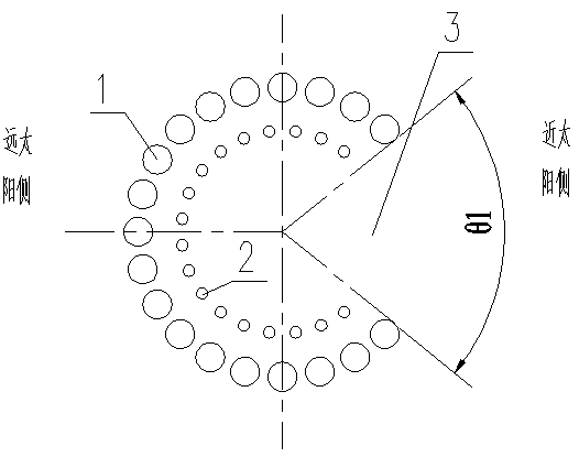
Examples

  • Experimental program(1)

Example Embodiment

[0020] The present invention will be further described in detail below with reference to the drawings and embodiments. The following embodiments are for explaining the present invention and the present invention is not limited to the following embodiments.
[0021] See attached Figure 1-Figure 5 The embodiment of the present invention includes a heat collector and a heliostat field.
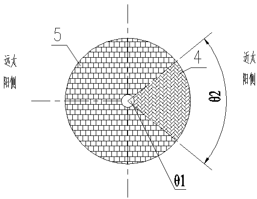
[0022] The heliostat field is divided into a near-solar heliostat field area 4 and a far-solar heliostat field area 5. The heliostat cosine loss in the near-solar heliostat field area 4 is higher than that of the far-solar heliostat field area 5. The mirror is large, so more heliostats can be arranged in the far-sun heliostat field 5 to improve the reflection efficiency of the entire heliostat. The near-solar heliostat field area 4 and the far-solar heliostat field area 5 divide the entire heliostat field into two fan-shaped areas. The angle of the fan-shaped area formed by the near-solar heliostat field area 4 is θ2. The angle of the fan-shaped area formed by the solar heliostat field area 5 is 360°-θ2.
[0023] The heat collector includes an external heat absorption tube group, an internal heat absorption tube group, a selective absorption coating 11, a selective absorption coating 2 12, a selective absorption coating 3 21, and a selective absorption coating 4 22. The external heat absorption tube group is composed of the external heat absorption tube 1 and the internal heat absorption tube group is composed of the internal heat absorption tube 2.
[0024] The external heat absorption tube 1 is arranged outside the internal heat absorption tube 2, and the external heat absorption tube 1 and the internal heat absorption tube 2 are distributed in staggered rows.
[0025] The outer heat-absorbing tube group and the inner heat-absorbing tube group are arranged concentrically. The external heat-absorbing tube group is an outer surface light-receiving collector that absorbs solar energy, and a cavity structure is constructed for the internal heat-absorbing tube 2, so that the radiation heat loss of the inner and outer heat-absorbing tubes can be mutually absorbed, Improve the thermal efficiency of the collector; the internal heat absorption tube group is similar to a cavity type collector. The above structure forms a new type of cavity-column heat collector. The cavity-column heat collector has the advantages of a cylindrical outer surface light-receiving collector that makes full use of the land area around the collector tower, and has a cavity-type heat collector The advantages of small radiation and convection heat loss, so the thermal efficiency of the entire collector can be significantly improved. The outer heat absorption tube group is provided with an opening for the outer heat absorption tube group, and the inner heat absorption tube group is provided with an opening for the inner heat absorption tube group. The outer heat absorption tube group opening and the inner heat absorption tube group opening are combined to form a fan-shaped opening 3, and a fan-shaped opening 3 The angle of is θ1.
[0026] There are gaps between the external heat absorption tube 1 and the internal heat absorption tube 2, between two adjacent tubes in the external heat absorption tube 1, and between two adjacent tubes in the internal heat absorption tube 2.
[0027] When water is used as the heat transfer medium, the external heat absorption tube 1 constitutes a steam evaporator for preheating and evaporative heating of low-temperature feed water, and the internal heat absorption tube 2 constitutes a steam superheater for converting saturated steam into superheated steam. The independent arrangement of the working fluid evaporation section and the superheat section makes the entire heat absorption system simpler, more economical and safer; at the same time, the solar radiation heat received by the external heat absorption tube 1 and the internal heat absorption tube 2 can be distributed by adjusting the angle θ1 of the fan-shaped opening 3 , To ensure the hydrodynamic stability of the heat exchange of the working fluid in the collector. It is easy to know that the heating heat required for external preheating and evaporative heating is much greater than the overheating heat. Therefore, the fan-shaped opening 3 faces the near-solar heliostat field area 4, and the far-solar heliostat field area 5 matches the external heat absorption tube 1, which is near the sun. The field area 4 of the heliostat matches with the internal heat absorption tube 2. The external heat absorption tube 1 and the internal heat absorption tube 2 correspond to different areas of the heliostat field, which can effectively reduce the difficulty of the heliostat field tracking control system. At the same time, the angle θ2 of the fan-shaped area of ​​the near-solar heliostat field 4 can be adjusted. , To distribute the solar radiation heat received by the external heat absorption tube 1 and the internal heat absorption tube 2 to further enhance the hydrodynamic stability of the heat exchange of the working fluid in the heat collector. The angle θ1 of the fan-shaped opening 3 is the same as the angle θ2 of the fan-shaped area of ​​the near-solar heliostat field 4, which improves the efficiency of absorbing heat energy. The angle θ1 of the fan-shaped opening 3 and the angle θ2 of the fan-shaped area of ​​the near-solar heliostat field 4 can be adjusted simultaneously to enhance the flexibility and safety of the entire heat exchange system.
[0028] The selective absorption coating 11 is applied to the half circumference of the outer heat absorption tube 1 far from the sun, and the selective absorption coating 2 12 is applied to the half circumference of the outer heat absorption tube 1 near the sun. The selective absorption coating 3 21 is coated on the half circumference of the inner heat absorbing tube 2 on the far sun side, and the selective absorption coating 422 is coated on the half circumference of the inner heat absorbing tube 2 near the sun.
[0029] The absorption rate of the selective absorption coating 11 and the selective absorption coating 2 12 are different, and the absorption rate of the selective absorption coating 321 and the selective absorption coating 422 are different. Due to the angle of the fan-shaped opening 3 on the half circumference of the inner heat absorption tube 2 near the sun, and the heliostat cosine loss in the near-solar heliostat field 4 is larger than that of the far-solar heliostat field 5, The near-sun side mirror field itself reflects less light, so the selective absorption coating 422 can be set to a high absorptivity, which can be set to 0.9; the far sun heliostat field area 5 mirror field cosine loss is small, the mirror field Large, the absorption rate of the selective absorption coating 321 on the half circumference of the inner heat absorption tube 2 far from the sun is lower than that of the selective absorption coating 422, which is set to 0.6-0.7, so that the internal heat absorption tube 2 has a circumferential heat flow distribution The uniformity is increased; the unabsorbed sunlight can be absorbed by the half circumference of the outer heat absorption tube 1 near the sun through reflection, and there is no loss of solar energy. In order that the half circumference of the outer heat absorption tube 1 near the sun side can absorb more reflected light, the selective absorption coating 2 12 can be set to a high absorption rate, and the absorption rate can be set to 0.9, so that the outer heat absorption tube 1 has a circumferential heat The uniformity is better; the outer heat absorption tube 1 has a large mirror field on the half circle far away from the sun and absorbs more solar energy. From the perspective of circumferential uniformity, the selective absorption coating 11 has a higher absorption rate than the selective absorption coating 2 12 is low, set to 0.8, although the total solar energy will be lost, but the circumferential heat flow distribution is better.
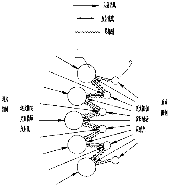
[0030] For the external heat-absorbing tube 1, the received energy of the half-circle on the far solar side is the incident light reflected by the far solar heliostat field area 5, and the half-circle on the near sun side receives energy in three parts, and the first part is the near solar fixed The solar light reflected by the heliostat field area 4 passes through the gap between the two adjacent tubes in the internal heat absorption tube 2. The second part is the solar incident light reflected by the far solar heliostat field area 5 through the external absorption. The gap between the two adjacent tubes of the heat pipe 1 irradiates the reflected light of the half circumference of the inner heat absorbing tube 2 far from the sun, and the third part is the heat radiation of the half circumference of the inner heat absorbing pipe 2 far from the sun. As for the inner heat-absorbing tube 2, the half-circle on the far sun side receives energy in three parts. The first part is the solar light reflected by the far solar heliostat field 5 passing through the gap between two adjacent tubes in the outer heat-absorbing tube 1. The second part is the solar incident light reflected by the near-solar heliostat field area 4 and irradiates the semicircle near the sun of the outer heat-absorbing tube 1 through the gap between two adjacent tubes in the inner heat-absorbing tube 2 The third part is the heat radiation of the half-circle near the sun side of the outer heat-absorbing tube 1, and the half-circle near the sun side of the inner heat-absorbing tube 2 receives energy from the sun incident reflected by the near-solar heliostat field 4 Light. Table 1 shows the heating conditions of the external heat absorption tube 1 and the internal heat absorption tube 2.
[0031] Table 1 The heating condition of the external heat absorbing pipe 1 and the internal heat absorbing pipe 2
[0032]
[0033] It can be seen from Table 1 that the heat received by the outer half-circumference of the outer heat-absorbing pipe 1, the inner half-circle of the inner heat-absorbing pipe 2 on the far sun side and the near sun side are all solar incident light, and there is no absolute backlight surface. 1. The uniformity of the 2 circumferential heat flow distribution of the internal heat absorption tube is improved. By optimizing the gap between the external heat absorption tube 1 and the internal heat absorption tube 2, the gap between two adjacent tubes in the external heat absorption tube 1, the gap between two adjacent tubes in the internal heat absorption tube 2, and the external absorption tube The heat pipe 1 and the internal heat absorption pipe 2 diameter specifications, etc., distribute the solar radiation irradiated on the external heat absorption pipe 1 and the internal heat absorption pipe 2 so that the external heat absorption pipe 1 and the internal heat absorption pipe 2 are circumferentially The unevenness of the heat flow distribution is further reduced.
[0034] In addition, by adjusting the absorptivity and reflectivity of the selective absorption coating 11, the selective absorption coating 2 12, the selective absorption coating 3 21, and the selective absorption coating 29 22, the external heat absorption pipe 1 can be further increased. , The uniformity of the 2 circumferential heat flow distribution of the internal heat absorption tube effectively reduces the temperature difference in the circumferential direction of the heat absorption tube, thereby reducing the material selection requirements of the heat absorption tube and reducing the initial investment cost of the heat collector. At the same time, the external heat absorption tube 1 and the internal heat absorption tube 2 mutually absorb part of the heat dissipation loss of each other, which can further improve the thermal efficiency of the heat collector. According to the actual temperature characteristics of the external heat absorption tube 1 and the internal heat absorption tube 2, different pipe materials can be selected to further reduce the initial investment cost of the collector.
[0035] In addition, it should be noted that, in the specific embodiments described in this specification, the shapes and names of the parts and components may be different, and the above content described in this specification is merely an example of the structure of the present invention. All equivalent changes or simple changes made according to the structure, features and principles described in the concept of the patent of the present invention are included in the protection scope of the patent of the present invention. Those skilled in the art to which the present invention pertains can make various modifications or additions to the specific embodiments described or substitute similar methods, as long as they do not deviate from the structure of the present invention or exceed the scope defined by the claims. All should belong to the protection scope of the present invention.

PUM

no PUM

Description & Claims & Application Information

We can also present the details of the Description, Claims and Application information to help users get a comprehensive understanding of the technical details of the patent, such as background art, summary of invention, brief description of drawings, description of embodiments, and other original content. On the other hand, users can also determine the specific scope of protection of the technology through the list of claims; as well as understand the changes in the life cycle of the technology with the presentation of the patent timeline. Login to view more.

Similar technology patents

Method and system for implementing translucent effect

ActiveCN102739983AConvenient mouse interaction responseReduce difficulty
Owner:TENCENT TECH (SHENZHEN) CO LTD

Switch power supply and its lossless absorption circuit

ActiveCN1734918AReduce spike voltageLower selection requirements
Owner:航天智讯新能源(山东)有限公司

Joint mercury removing method and device based on SNCR

ActiveCN105268300ASimple and economical processReduce initial investment cost
Owner:CHINA HUANENG GRP CO LTD +1

Classification and recommendation of technical efficacy words

  • Lower selection requirements

Switch power supply and its lossless absorption circuit

ActiveCN1734918AReduce spike voltageLower selection requirements
Owner:航天智讯新能源(山东)有限公司
Why Eureka
Try Eureka