Secondary light concentrating reflection-uniform heat flow trough type solar heat collector

A trough-type solar energy and secondary concentrating technology, which is applied to solar collectors, solar collectors using working fluids, solar thermal energy, etc., can solve the problem of uneven distribution of heat flux density in the circumferential direction of the collector tube and affect the heat collector Heat collection efficiency, heat collection tube mechanical damage and other issues, to achieve the effect of solving thermal stress damage, improving heat collection efficiency, and low cost

Active Publication Date: 2020-10-30
XI AN JIAOTONG UNIV
View PDF13 Cites 1 Cited by
  • Summary
  • Abstract
  • Description
  • Claims
  • Application Information

AI Technical Summary

Problems solved by technology

In the present invention, a special optically designed secondary reflector is added above the vacuum heat collecting tube. Without changing the basic configuration of the original trough solar heat collector, the luminous flux transfer is realized through the secondary reflector, so that the surrounding area of ​​the heat collecting tube Uniform distribution of heat flux in the direction, so as to solve the problem of uneven distribution of heat flux in the circumferential direction of the collector tube in traditional trough collectors, resulting in large thermal stress or even bending deformation, affecting the heat collection efficiency of the collector, and even causing mechanical damage to the collector tube, etc. technical problem

Method used


Image

  • Secondary light concentrating reflection-uniform heat flow trough type solar heat collector
  • Secondary light concentrating reflection-uniform heat flow trough type solar heat collector
  • Secondary light concentrating reflection-uniform heat flow trough type solar heat collector

Examples


Embodiment Construction

[0024] The present invention will be described in detail below in conjunction with the accompanying drawings and embodiments, without limiting the invention.

[0025] A specific example of the design will be described below.

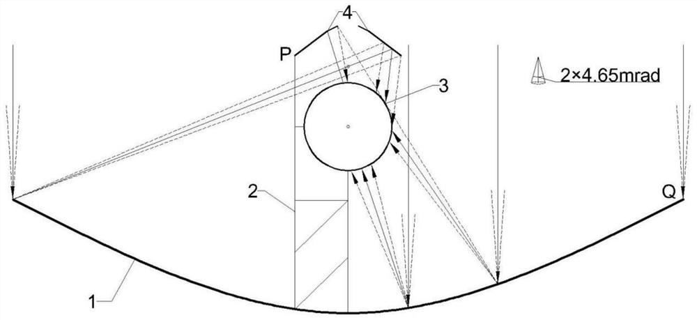
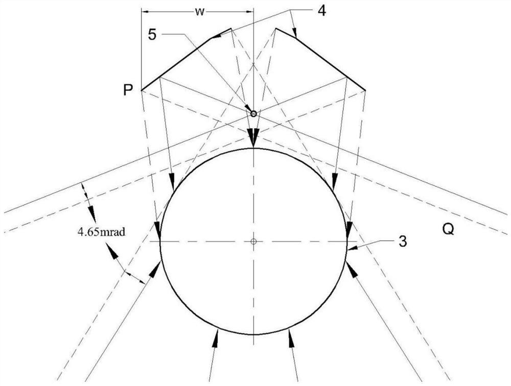
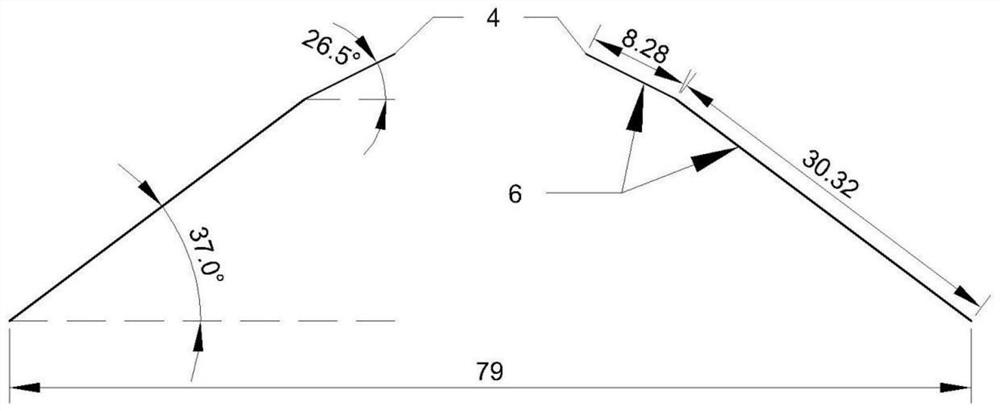
[0026] Such as figure 1 As shown, the secondary concentrating reflection-uniform heat flow trough solar collector provided by the present invention includes a parabolic trough reflector 1, a reflector support 2, a vacuum heat collecting tube 3 and a secondary composite plane reflector 4, and the vacuum collector The heat pipe 3 and the secondary composite plane reflector 4 are erected on the reflector bracket 2 . The length of the parabolic trough reflector unit is 4m, 6m or 7.8m, the opening width is 5m, the focal length is 1.84m; the outer diameter of the vacuum heat collecting tube is 70mm. The sunlight is actually a cone-shaped light. When the half-vertex angle of the sunlight cone is 4.65mrad, a small part of the approximately parallel sunlight is...


PUM


Abstract

The invention discloses a secondary light concentrating reflection-uniform heat flow trough type solar heat collector. The heat collector comprises a parabolic trough reflector, a reflector bracket, avacuum heat collection tube and a secondary composite plane reflector, wherein the secondary composite plane reflector and the vacuum heat collection tube are placed above and below the focal line ofthe parabolic trough reflector respectively, and a small part of sunlight is irradiated at intervals to the sun-facing wall face of the vacuum heat collection tube through the inner side of the secondary composite plane reflector; primary condensing of the remaining part of the light is completed through the parabolic trough reflector, and a part of the light is reflected to the downsun wall faceof the vacuum heat collection tube; and a part of the light is reflected to the sun-facing wall face of the vacuum heat collection tube through the secondary composite plane reflector to complete secondary condensing. The heat collector achieves uniform irradiated luminous flux on the wall face in the circumferential direction of the vacuum heat collection tube, solves the problem of uneven distribution of the circumferential heat flux density of a heat collection tube in a traditional trough type heat collector, and effectively reduces thermal stress damage of the heat collection tube, the modification process is simple, and the cost is low.

Description

technical field [0001] The invention belongs to the technical field of solar thermal utilization, in particular to a secondary concentrating reflection-uniform heat flow trough solar heat collector. Background technique [0002] Solar energy is the most abundant and clean renewable energy source on earth. The sum of the energy falling on the earth every hour is about the world's total annual energy consumption. The efficient, safe and low-cost utilization of solar energy can effectively solve the global energy problem. However, the current collection, conversion, distribution and final use of solar energy have economic and technical difficulties. The focus of solar thermal utilization is to convert solar energy into thermal energy and apply it to thermal power generation, thermochemical conversion, heating and cooling. According to the concentrated heat collection method, it can be divided into trough type, dish type and tower type. Among them, the trough type solar heat c...

Claims


Application Information

Patent Timeline
Patent Type & Authority Applications(China)
IPC IPC(8): F24S10/40F24S10/70F24S23/71F24S23/77
CPCF24S10/40F24S10/70F24S23/71F24S23/77F24S2023/87Y02E10/44
Inventor 杨卫卫唐鑫源白晓帅焦宇航阳昱叶苗
Owner XI AN JIAOTONG UNIV
Why Eureka
Try Eureka