A tower-type solar thermal power generation system based on a cavity-column collector

A tower solar and thermal power generation system technology, applied in solar thermal power generation, solar heating system, solar thermal energy and other directions, can solve the problem of difficult to achieve the temperature difference of the heat absorption pipe, reduce the selection requirements, reduce the initial investment cost and improve the thermal efficiency Effect

Active Publication Date: 2020-07-14
CHINA UNITED ENG
View PDF6 Cites 0 Cited by
  • Summary
  • Abstract
  • Description
  • Claims
  • Application Information

AI Technical Summary

Problems solved by technology

However, its disadvantages are: the outer heat absorbing tube and the inner heat absorbing tube only have direct sunlight on the half circle facing the mirror field, and only reflected sunlight on the half circle not facing the mirror field, and the inner heat absorbing tube There is no heat on the backlight surface, so although the problem of local overheating of the heat-absorbing pipe has been curbed to a certain extent, it is still difficult to achieve an ideal level of temperature difference between the heat-absorbing pipe on the light surface and the backlight surface

Method used


Image

  • A tower-type solar thermal power generation system based on a cavity-column collector
  • A tower-type solar thermal power generation system based on a cavity-column collector
  • A tower-type solar thermal power generation system based on a cavity-column collector

Examples


Embodiment Construction

[0020] The present invention will be further described in detail below in conjunction with the accompanying drawings and examples. The following examples are explanations of the present invention and the present invention is not limited to the following examples.

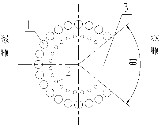
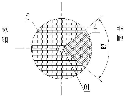
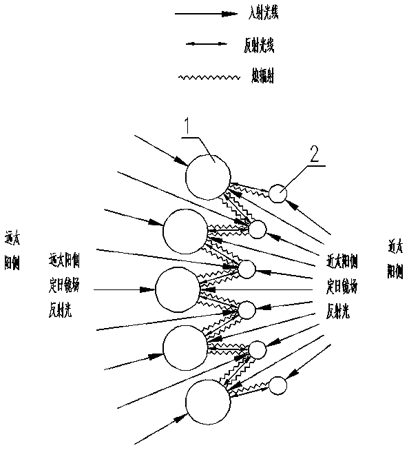
[0021] See attached Figure 1-Figure 5 , an embodiment of the invention comprising a collector and a field of heliostats.

[0022] The heliostat field is divided into the near-sun heliostat field area 4 and the far-sun heliostat field area 5, and the cosine loss of the heliostat in the near-sun heliostat field area 4 is greater than that of the far-sun heliostat field area 5. The mirror is large, so more heliostats can be arranged in the far-sun heliostat field area 5, so as to improve the reflection efficiency of the whole heliostat. The near-sun heliostat field area 4 and the far-sun heliostat field area 5 divide the entire heliostat field into two fan-shaped areas, and the angle of the fan-shaped area formed by ...


PUM


Abstract

The invention provides a cavity column type heat collector based tower type solar thermal power generation system which can effectively reduce front-rear temperature difference between a phototropic face and a shady face of a heat absorbing tube. An opening of an external heat absorbing tube group and an opening of an internal heat absorbing tube group are combined to form a fan-shaped opening; the fan-shaped opening faces towards a sun heliostat field region; a gap is formed between the external heat absorbing tube and the internal heat absorbing tube or between adjacent two tubes in the external heat absorbing tube or between adjacent two tubes in the internal heat absorbing tube; a selective absorbing coating I is coated on the semi-circumference of one side away from the sun of the external heat absorbing tube, a selective absorbing coating II is coated on the semi-circumference of one side away from the sun of the external heat absorbing tube, a selective absorbing coating III iscoated on the semi-circumference of one side away from the sun of the internal heat absorbing tube, and a selective absorbing coating IV is coated on the semi-circumference of one side away from the sun of the internal heat absorbing tube; and an absorption rate of the selective absorbing coating III is lower than that of the selective absorbing coating IV, and an absorption rate of the selectiveabsorbing coating I is lower than that of the selective absorbing coating II.

Description

technical field [0001] The invention relates to a tower-type solar thermal power generation system based on a cavity-column heat collector. Background technique [0002] In the past ten years, solar power generation has been a research hotspot all over the world, and its installed capacity under construction and completed has maintained an annual growth rate of 30%. Typical tower-type solar thermal power generation technology has high power generation efficiency due to the use of short pipelines, high concentration ratio, and steam with high parameters, and has been developed rapidly. [0003] The theoretical light concentration ratio of the tower power generation system exceeds 1000, and the light-facing surface of the heat-absorbing pipe needs to bear a high heat load, while the backlight surface is usually a thermal insulation structure. Therefore, the heat-absorbing tube receiving light on one side is prone to local overheating, and there is a large temperature differen...

Claims


Application Information

Patent Timeline
Patent Type & Authority Patents(China)
IPC IPC(8): F24S10/70F24S70/20F24S80/00F22G3/00
CPCF22G3/00F24S10/70F24S70/20F24S80/00Y02E10/44
Inventor 韩临武郭伟华钱怀洲张同翔查从念
Owner CHINA UNITED ENG
Why Eureka
Try Eureka