
Method for measuring periodic error of photoelectric range finder

A photoelectric range finder, period error technology, applied in measurement devices, instruments, optical devices, etc., can solve the problems of relatively high environmental requirements, high measurement environment and measurement methods, expensive purchase and maintenance, etc. Reliability, low workload, effect of eliminating influence

Active Publication Date: 2019-07-23
武汉地震计量检定与测量工程研究院有限公司
View PDF17 Cites 0 Cited by
  • Summary
  • Abstract
  • Description
  • Claims
  • Application Information

AI Technical Summary

Problems solved by technology

The following requirements need to be strictly met: 1. Length standards need to be used, and the accuracy of the length standards should generally be better than 0.1mm, so that the measurement error is much smaller than the amplitude of the periodic error; 2. The length standards relied on by existing methods Mainly standard steel tapes, grating rulers, laser interferometers, etc., are expensive to purchase and maintain; 3. The existing methods have relatively high environmental requirements during the measurement process; There are requirements for the flatness of the measuring platform, generally requiring its flatness to be better than 5×10 -5 , if you use a linear ruler, you also need to align the optical path
To sum up, the traditional periodic error measurement method of photoelectric rangefinders relies on expensive high-precision length standards, which have high requirements for the measurement environment and measurement methods. These measurement methods need to be improved urgently

Method used


Image

  • Method for measuring periodic error of photoelectric range finder
  • Method for measuring periodic error of photoelectric range finder
  • Method for measuring periodic error of photoelectric range finder

Examples


Embodiment Construction

[0041] The following will clearly and completely describe the technical solutions in the embodiments of the present invention in conjunction with the embodiments of the present invention. Obviously, the described embodiments are only part of the embodiments of the present invention, not all of them. Based on the implementation manners in the present invention, all other implementation manners obtained by persons of ordinary skill in the art without making creative efforts belong to the scope of protection of the present invention.

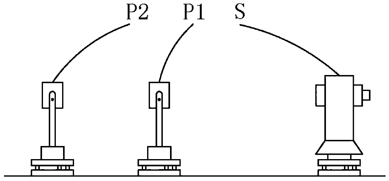
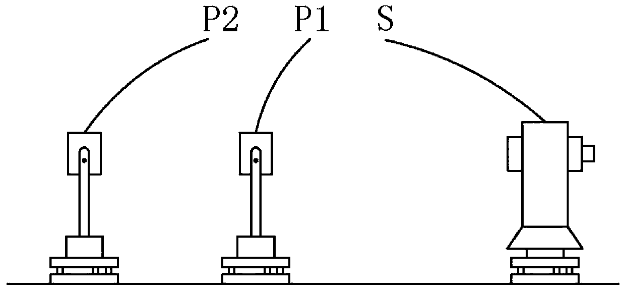
[0042] Such as figure 1 As shown, the present invention provides a kind of photoelectric range finder periodic error measurement method, comprises the following steps:

[0043] S1: Install the distance measuring prism P1 on the forced centering device to ensure that the erection position of the distance measuring prism P1 remains unchanged;

[0044] S2: Set the distance measuring prism P2 on the forced centering device, so that the distance measur...


PUM


Abstract

The invention provides a method for measuring a periodic error of a photoelectric range finder. The method comprises the following steps of setting two ranging prisms and a photoelectric range finder,keeping the relative positions of the two ranging prisms unchanged and the centers of the respective devices in equal height and common line, moving the photoelectric range finder and performing distance measurement on the two ranging prisms at each position, calculating the results of multiple distance measurement to solve the periodic error amplitude and the initial phase angle of the photoelectric range finder, and giving a standard deviation of the corresponding measurement. The method, without relying on a length standard device, uses a forced centering device and the ranging prisms to measure and calculate the related parameters of the periodic error amplitude and the initial phase angle, and the manual detection workload is small. The method does not require high measurement environment, has no need to meet harsh use conditions of auxiliary measuring equipment such as a standard steel tape, a grating ruler and a laser interferometer, and can eliminate the influence of linear errors on the measurement result, improve the reliability of the measurement result, and represent the measurement accuracy level by measuring the standard deviation.

Description

technical field [0001] The invention relates to the technical field of measurement performance detection of a photoelectric range finder, in particular to a method for measuring the periodic error of a photoelectric range finder. Background technique [0002] The photoelectric rangefinder is based on the known characteristics of the propagation speed of electromagnetic waves in the air. The distance value is obtained by testing the time for the electromagnetic wave to travel back and forth on the measured distance. The distance measurement methods mainly include phase method, pulse method, frequency conversion method, etc. . The distance measurement accuracy of the photoelectric rangefinder is an important indicator for the normal operation of the instrument. The distance measurement accuracy will be affected by the performance of the instrument, the measurement method and the outside world during the measurement. Periodic error refers to the error that occurs repeatedly ba...

Claims


Application Information

Patent Timeline
Patent Type & Authority Applications(China)
IPC IPC(8): G01B11/02
CPCG01B11/02
Inventor 刘海波刘正华郭若成张鑫武金凤汪洋舰
Owner 武汉地震计量检定与测量工程研究院有限公司
Learn More