
Visible soil destruction mode capture device

A failure mode and capture device technology, applied in the field of geotechnical engineering, can solve the problems of lack of accuracy in manual sand spreading, lack of multi-directional loading conditions, single loading method, etc., to achieve uniform and flexible arrangement of colored sand, efficient and labor-saving sand spreading , the effect of diversification

Inactive Publication Date: 2019-07-23
NORTHEASTERN UNIV
View PDF7 Cites 5 Cited by
  • Summary
  • Abstract
  • Description
  • Claims
  • Application Information

AI Technical Summary

Problems solved by technology

[0003] In the study of the failure form of building foundations, since the strength of the foundation is much greater than that of the soil, when the upper horizontal load is large or the lower soil layer is discontinuous and uniform, soil damage phenomena such as "soil arching effect" are likely to occur. The in-situ test is not only costly, but also can only observe the apparent phenomenon, and cannot further observe the interaction inside the soil directly. The model test can solve this problem very well.
[0004] The current test devices used to study soil damage mainly have the following problems: (1) The existing test devices lack a device that can evenly spread sand when building a soil model, and the soil of the natural foundation cannot be further accurately simulated during the test. The compactness of the body, or relying only on manual sanding lacks accuracy, and it is time-consuming and laborious
(2) Existing test devices usually only have a vertical loading system with a single loading method and do not have multi-directional loading conditions
(3) The existing test device does not have a measurement function when observing rock and soil failure phenomena, and cannot directly observe the moving distance of the soil body
(4) The existing test device lacks a device for evenly distributing colored sand when building a soil model, and cannot flexibly switch between laying out colored sand and ordinary sand
(5) The existing test device lacks a sand unloading device, and manual sand unloading is time-consuming and laborious

Method used


Image

  • Visible soil destruction mode capture device
  • Visible soil destruction mode capture device
  • Visible soil destruction mode capture device

Examples


Embodiment 1

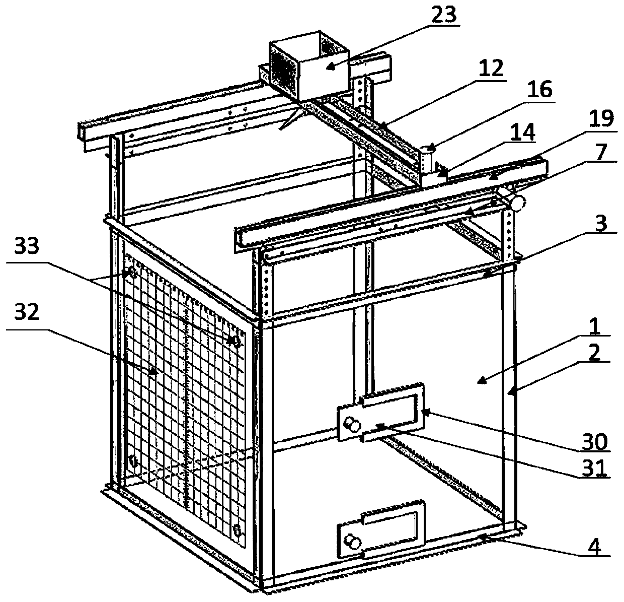
[0040] A visual soil failure mode capture device, which consists of a soil model box, a loading system, a sand spreading device, a sand unloading device and a magnetic scale plate. The loading system and the sand spreading device are arranged above the soil model box. The loading system includes a horizontal The loading device, the vertical loading device, the sand unloading device and the magnetic scale plate are respectively arranged on the adjacent two sides of the model box, and the sand spreading device can move left and right, front and rear above the soil model box and sprinkle sand into the model box. The horizontal loading device relies on the first separate short-type hydraulic jack to push the piston rod forward through pressurization, thereby applying pressure to the model, and forming a reaction force structure through the interaction of the outer support frame to maintain its own stability. The vertical loading device relies on the second separated short hydraulic...

Embodiment 2

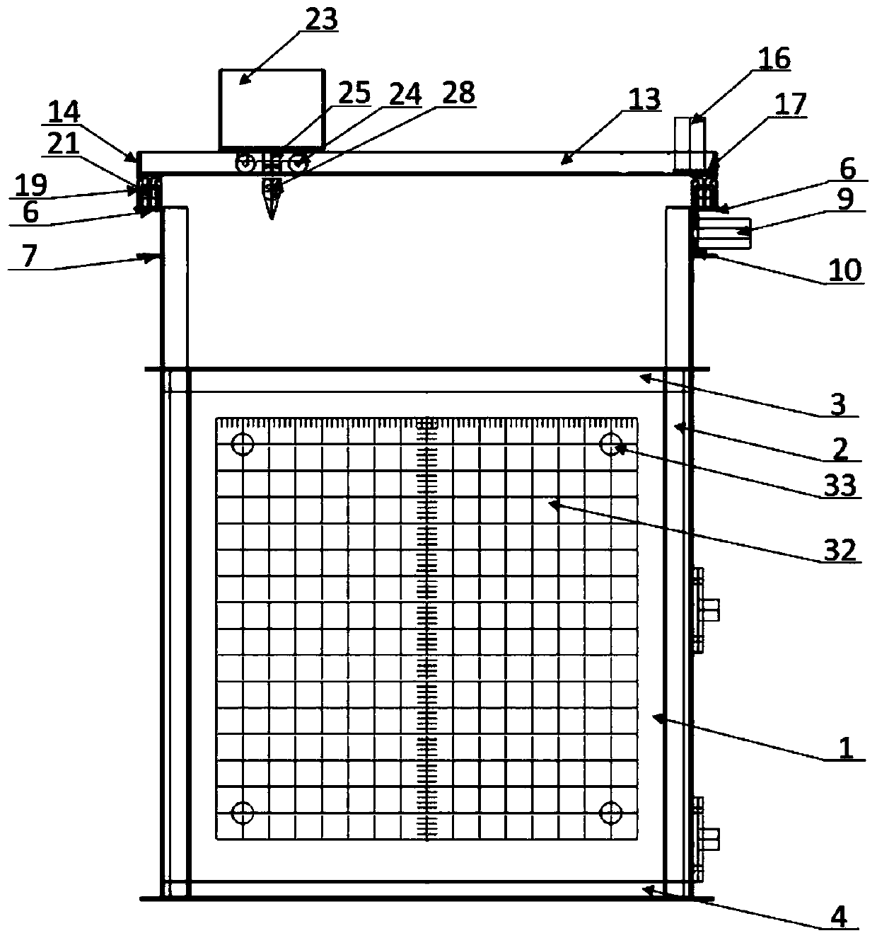
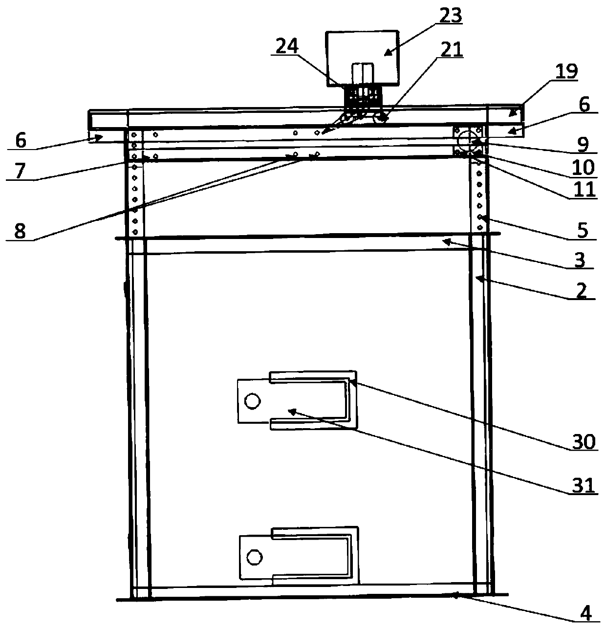
[0047] This embodiment is based on Embodiment 1, and further optimizes the visual soil failure mode capture device. The structural diagram of the visual soil failure mode capture device is as follows figure 1 As shown, specifically, the soil model box is composed of a box body and an outer support frame. The box body 1 is composed of 5 transparent square transparent polyester resin boards with a thickness of h. The area of ​​the 5 polyester resin boards is L×L, and each of the bottom, front, rear, left and right sides is glued together. A cube without a cover on the upper part is formed to accommodate the model soil. The outer support frame is composed of 12 angle steels, which are welded to form a space cube that is tightly wrapped around the box to prevent the box from being damaged by force and provide counterforce support for the loading system. like figure 2 and image 3 As shown, four vertical angle steels 2 are arranged at the four corners of the model box, the leng...


PUM


Abstract

The invention relates to a visible soil destruction mode capture device. The visible soil destruction mode capture device comprises a model box, a loading system, a sand scattering device, a sand unloading device, and a magnetic scale board, wherein the loading system and the sand scattering device are above the model box, the loading system comprises a horizontal loading device and a vertical loading device, the sand unloading device and the magnetic scale board are respectively arranged at two adjacent sides of the model box, and the sand scattering device can move above the model box left and right and front and back and scatters sand into the model box. The visible soil destruction mode capture device can scatter sand uniformly, efficiently and effortlessly and unloads sand rapidly, can simulate compactness of natural soil accurately, deploys color sand uniformly and flexibly, can perform vertical and horizontal load simultaneously in different positions, and enables operators to observe intuitively soil destruction phenomena like 'soil arching', destruction face mode of an active face, and destruction mode of a composite foundation.

Description

technical field [0001] The invention relates to a visual soil failure mode capture device, which belongs to the technical field of geotechnical engineering. Background technique [0002] With the continuous advancement of the current infrastructure construction, geotechnical engineering technology has been vigorously developed. In the process of theoretical analysis calculation and numerical simulation test of geotechnical engineering problems, its important parameters need to be obtained through engineering tests. The indoor test platform is often used first to carry out similar model tests because of its resource saving, accuracy and reliability, and repeatable verification results. [0003] In the study of the failure form of building foundations, since the strength of the foundation is much greater than that of the soil, when the upper horizontal load is large or the lower soil layer is discontinuous and uniform, soil damage phenomena such as "soil arching effect" are l...

Claims


Application Information

Patent Timeline
IPC IPC(8): G01N3/12
CPCG01N3/12G01N2203/0019G01N2203/0048G01N2203/0067G01N2203/0258G01N2203/0298G01N2203/0682
Inventor 赵文陈阳金文强韩健勇贾鹏蛟金陈王鑫夏志康
Owner NORTHEASTERN UNIV
Learn More