Rotary load smooth control method based on magnetic suspension bearing active stiffness regulation

A magnetic suspension bearing and smooth control technology, applied in attitude control and other directions, can solve problems such as the inability to achieve precise modeling of magnetic suspension bearing stiffness and active regulation of low stiffness.

Active Publication Date: 2019-07-23
HARBIN INST OF TECH
View PDF8 Cites 4 Cited by
  • Summary
  • Abstract
  • Description
  • Claims
  • Application Information

AI Technical Summary

Problems solved by technology

[0005] The purpose of the present invention is to solve the problem that the existing method cannot realize the fine modeling of the stiffness of the magnetic suspension bearing with the stator floating in space and the active regulation of its low stiffness

Method used


Image

  • Rotary load smooth control method based on magnetic suspension bearing active stiffness regulation
  • Rotary load smooth control method based on magnetic suspension bearing active stiffness regulation
  • Rotary load smooth control method based on magnetic suspension bearing active stiffness regulation

Examples


specific Embodiment approach 1

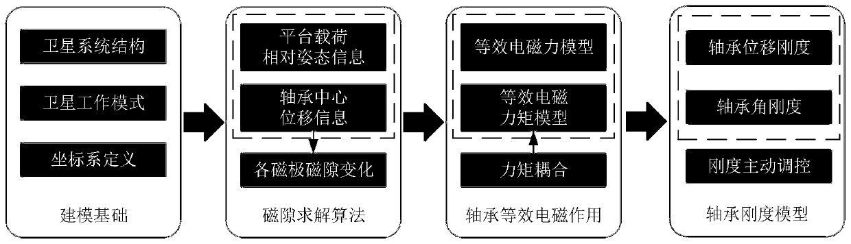
[0022] Specific implementation mode one: combine figure 1 This embodiment will be described. The method for stabilizing rotating loads based on the active stiffness regulation of the magnetic suspension bearing described in this embodiment includes the following steps:

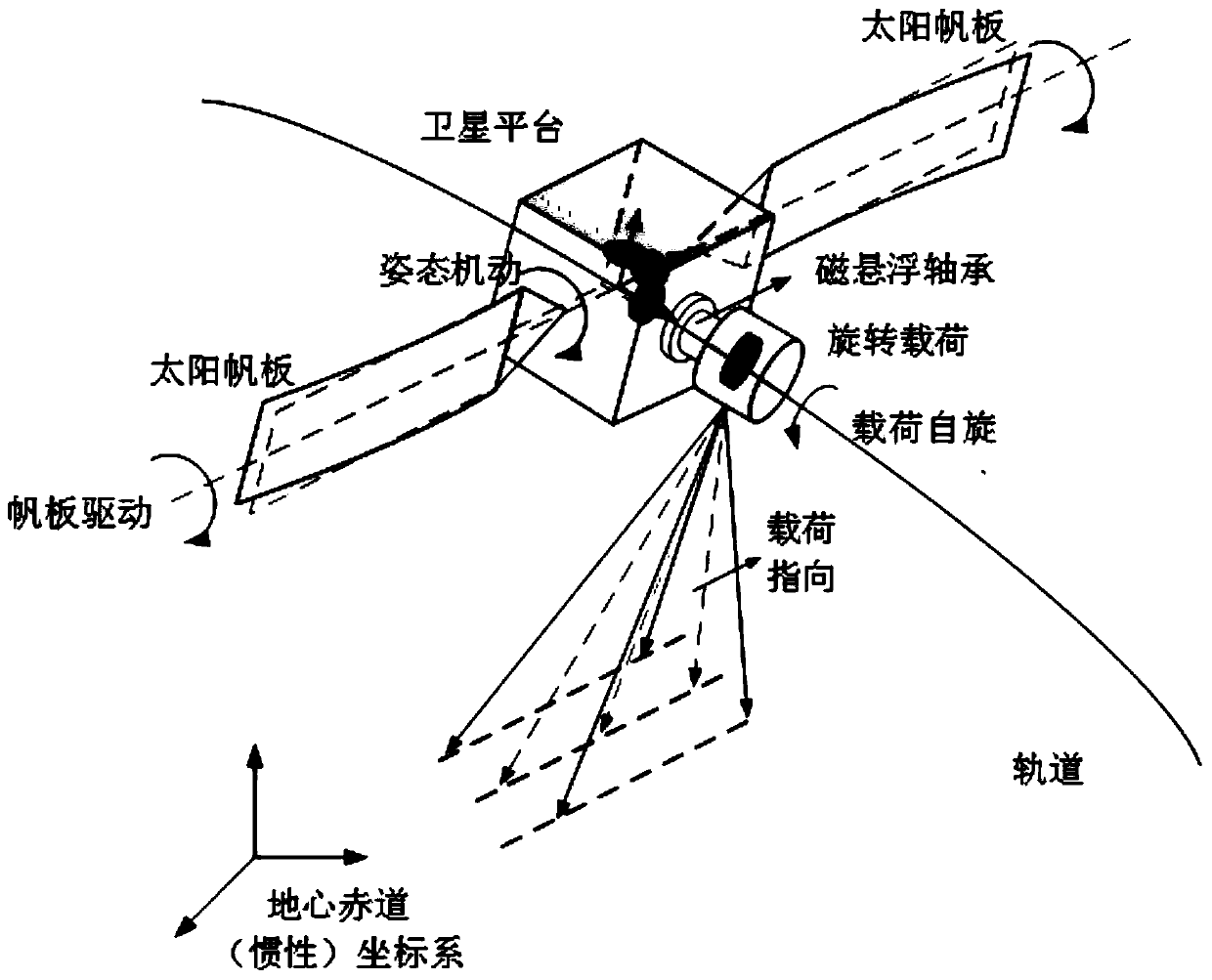
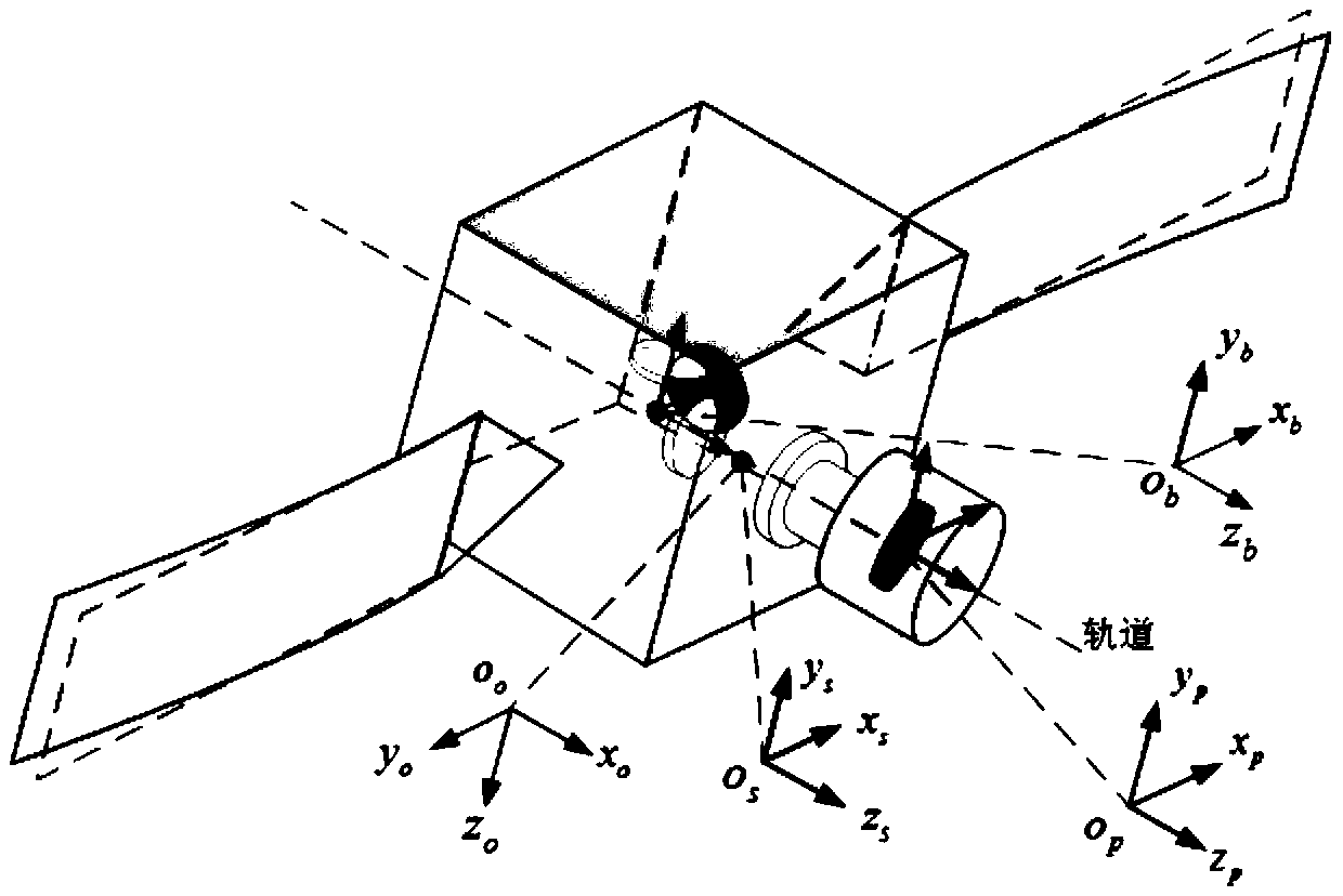
[0023] Step 1. Determine the composition and working mode of the rotating payload satellite system, and define the geocentric equatorial coordinate system oxyz and the orbital coordinate system o o x o the y o z o , The barycentric coordinate system of the rotating payload satellite system o s x s the y s z s , Satellite platform body coordinate system o b x b the y b z b and rotating load body coordinate system o p x p the y p z p ;

[0024] Step 2. According to the spatial relative attitude information of the satellite platform and the rotating load and the displacement information of the center of the magnetic levitation bearing (that is, the center position of the thrust disc or the middle ...

specific Embodiment approach 2

[0031] Specific implementation mode two: the difference between this implementation mode and specific implementation mode one is: the specific process of the step one is:

[0032] Such as figure 2As shown, the structure of the satellite system for determining the rotating load includes the satellite platform subsystem, the load subsystem and the rotary joint; the satellite platform subsystem includes: the satellite platform, the platform three-axis orthogonal flywheel and the platform double-sided solar panels; The load subsystem further includes: a rotating load and a flywheel within the load; the rotating joint is a magnetic suspension bearing (and equipped with a mechanical bearing and a drive motor), and the magnetic suspension bearing is composed of a left radial bearing, a right radial bearing, an axial bearing and a rotating shaft Composition, the stator part of the magnetic suspension bearing is fixedly connected with the satellite platform subsystem, and the rotor pa...

specific Embodiment approach 3

[0040] Specific implementation mode three: combination Figure 4 This embodiment will be described. The difference between this embodiment and the second embodiment is that the specific process of the second step is:

[0041] Define the vector r 5 Represents the position vector of the desired center of the magnetic suspension bearing pointing to the current center of the magnetic suspension bearing, vector r 6 Represents the position vector of the current center of the magnetic suspension bearing pointing to the action point of the left radial bearing, vector r 7 Represents the position vector where the expected center of the magnetic suspension bearing points to the action point of the left radial bearing, vector r 8 Represents the position vector of the current center of the magnetic suspension bearing pointing to the action point of the right radial bearing, vector r 9 Represents the position vector of the expected center of the magnetic suspension bearing pointing to t...


PUM


Abstract

The invention provides a rotary load smooth control method based on magnetic suspension bearing active stiffness regulation, and belongs to the field of spacecraft bearing joint stiffness modeling andcontrol. The invention solves the problem that the magnetic suspension bearing stiffness fine modeling of stator space floating and the active regulation of low stiffness cannot be realized by usingan existing method. According to a working mode and structure characteristics of a rotary load satellite system, an algorithm is designed to solve the magnetic gap change of each magnetic pole according to the displacement change of a bearing center and spatial relative attitude information of a satellite platform and a rotary load, so that an electromagnetic action model which is equivalent to the center of a magnetic suspension bearing is established according to an electromagnetic theory, a magnetic suspension bearing stiffness model is obtained by solving, and then controller parameters are designed according to the rigidity model to carry out low-stiffness active regulation, so that the smooth control of the rotary load is realized. The rotary load smooth control method based on the magnetic suspension bearing active stiffness regulation provided by the invention can be applied to the field of spacecraft bearing joint stiffness modeling and control.

Description

technical field [0001] The invention belongs to the field of modeling and control of joint stiffness of spacecraft bearings, and in particular relates to a high-stability and stable control method for rotating load attitude on a remote sensing satellite based on the active stiffness control technology of a magnetic suspension bearing. Background technique [0002] With the increasing demands of space missions, the requirements for the attitude stability of remote sensing satellite payloads are getting higher and higher. In order to improve the spin accuracy of the rotating load on the remote sensing satellite and suppress the high-frequency vibration transmission of the satellite, at this stage, the magnetic suspension bearing with lower stiffness (compared to the mechanical bearing) is applied to the remote sensing satellite system as the load connection joint to realize the soft connection. application prospects. [0003] Magnetic suspension bearing is a non-contact beari...

Claims


Application Information

Patent Timeline
Patent Type & Authority Applications(China)
IPC IPC(8): G05D1/08
Inventor 曹喜滨魏承赵亚涛王峰
Owner HARBIN INST OF TECH
Why Eureka
Try Eureka