Rotation disc-type motor structure
A motor structure, turntable technology, applied in synchronous motors with static armatures and rotating magnets, electrical components, electromechanical devices, etc. Performance requirements, reduced strength requirements, and the effect of increasing power density
- Summary
- Abstract
- Description
- Claims
- Application Information
AI Technical Summary
Problems solved by technology
Method used
Image

Examples
Embodiment 1
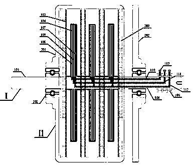
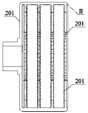
[0033] see Figure 1~Figure 5 , the pair of turntable motors includes a fusion shaft structure (I), an integrated casing structure (II) and a support bearing (102), and is characterized in that: the fusion shaft structure (I) is composed of windings of each phase (105~107) The inner end is connected to the external brush slip ring (109, 113) for power supply through the shaft groove (110~112); meanwhile, the integrated shaft structure (I) is contained in the integrated casing structure (II) and supported by the supporting bearing (102) support; the integrated casing structure (II) is connected with the casing (201) by the outer end of the permanent magnet (202); the integrated shaft structure (I) winding and the integrated casing structure (II) permanent magnets are mutually The electromagnetic force generated by the action drives the two to move in opposite directions, realizing the counter-rotation function of the disc motor, which can realize bidirectional power output, and...
Embodiment 2
[0034] Embodiment two, this embodiment is basically the same as embodiment one, and the special features are as follows:
[0035] The phase winding fixing method of the integrated rotating shaft structure (I) includes but is not limited to, the winding is embedded in the rotating shaft (101) to fix; or the outer layer of the winding is covered with support material and fixed to the rotating shaft (101); or the winding is fixed by bonding material Fixed with the shaft. The supporting material used for winding fixation: including but not limited to, using carbon fiber or aramid fiber high-strength material to weave, or bind, or wrap, etc. to fix and increase the structural strength. The rotating shaft (101) in the integrated rotating shaft structure (I): including but not limited to, grooves on the surface or inside of the rotating shaft (101) to provide physical connection channels between windings of each phase and external circuits. The integrated casing structure (II) is co...
Embodiment 3
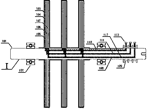
[0037] Figure (2) shows the integrated rotating shaft structure in the implementation example of the present invention, which is composed of a slotted rotating shaft (401) and windings (105~107) of each phase.
[0038] Further, the rotating shaft involved in the examples of the present invention may have one or more grooves on the surface or inside. The polyphase wires drawn out from the winding are connected to the brush slip ring outside the rotating shaft along the groove, and the inner surface of the groove can be coated with insulating material (108) to enhance the insulation level between the groove of the rotating shaft and the winding. The outer surface of the thread-embedded shaft can use high-strength materials such as carbon fiber and aramid fiber (103, 104) to increase the structural strength by covering, binding, etc., and reduce the risk of strength decline caused by the slotting of the shaft.
[0039] Based on the large effective diameter of the inner end of the...
PUM
 Abstract
Description
Claims
Application Information
 - R&D
- Intellectual Property
- Life Sciences
- Materials
- Tech Scout
- Unparalleled Data Quality
- Higher Quality Content
- 60% Fewer Hallucinations
Browse by: Latest US Patents, China's latest patents, Technical Efficacy Thesaurus, Application Domain, Technology Topic, Popular Technical Reports.
© 2025 PatSnap. All rights reserved.Legal|Privacy policy|Modern Slavery Act Transparency Statement|Sitemap|About US| Contact US: help@patsnap.com