
Compatible vehicle-mounted microphone circuit

A microphone and compatible technology, which is applied in the field of compatible vehicle microphone circuits, can solve the problems of microphones not being used normally, inconvenience, passengers' harsh sound, etc., and achieve the effect of satisfying individual selection, simple circuit, and reducing switching noise

Active Publication Date: 2019-07-23
XIAMEN YAXON NETWORKS CO LTD
View PDF11 Cites 0 Cited by
  • Summary
  • Abstract
  • Description
  • Claims
  • Application Information

AI Technical Summary

Problems solved by technology

The condenser microphone, also called an electret microphone, its core component is the stage head, which is composed of two metal films; when the sound wave causes it to vibrate, the difference in the distance between the metal films causes the difference in capacitance, thereby generating a current. It uses the change of capacitance to convert the sound signal into an electrical signal. It must be driven by an independent power supply, generally 1.5V. If the two microphones are input on the same interface, and the input circuit is not compatible design, it will cause inconvenience in actual use, or cause a problem that the microphone cannot be used normally
[0004] In addition, when these two microphones are actually used, there is often a "pop" sound when the microphone is turned on. For this kind of switching noise, if it is not dealt with, it will often bring a harsh sound to passengers.
In view of these problems, a circuit and method compatible with vehicle-mounted dynamic microphones and condenser microphones are needed to solve the compatibility problems of these two microphones in actual use and to optimize the noise problem.

Method used


Image

  • Compatible vehicle-mounted microphone circuit
  • Compatible vehicle-mounted microphone circuit

Examples


Embodiment Construction

[0024] The present invention will be further described below through specific embodiments.

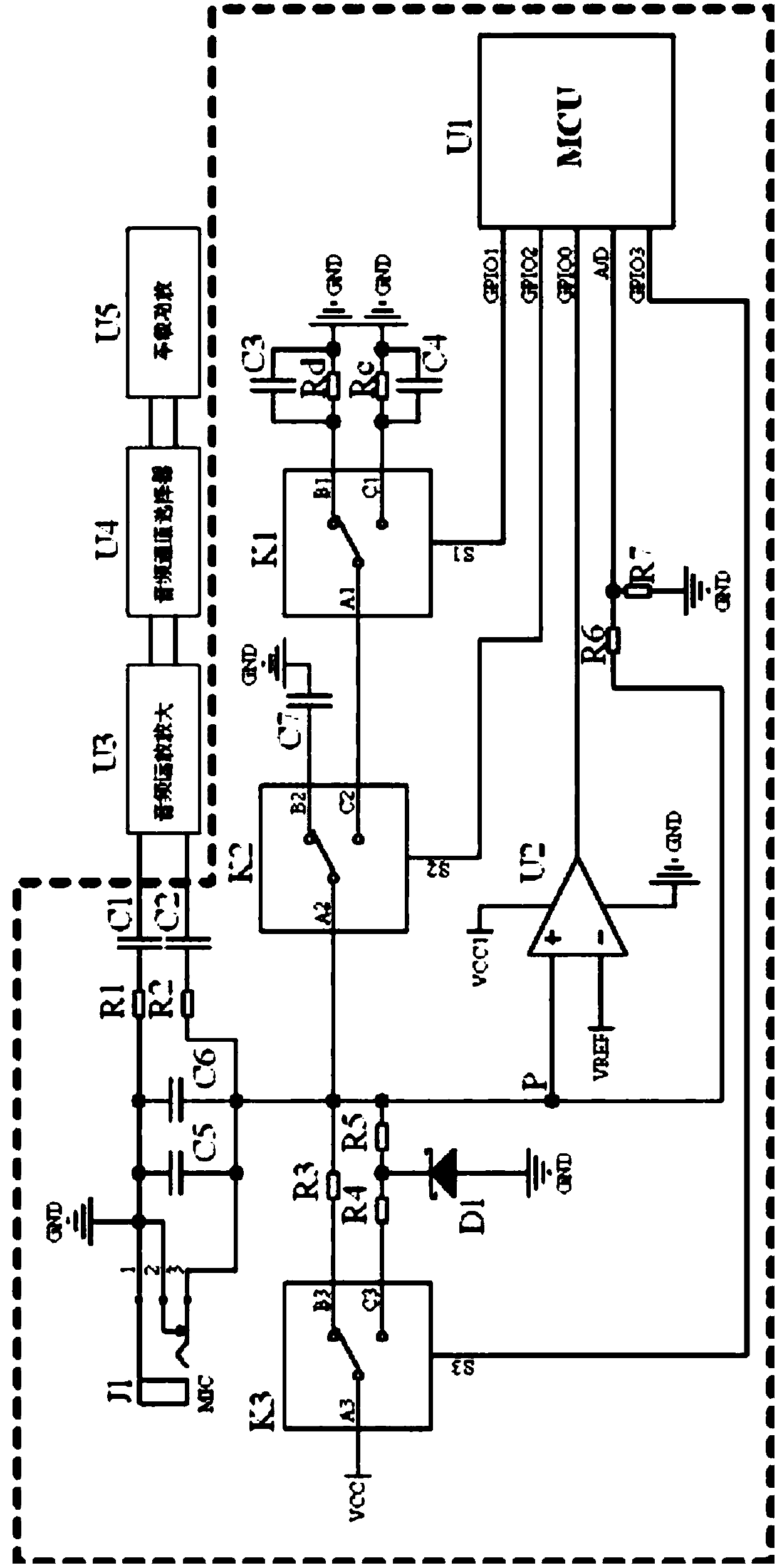
[0025] refer to figure 1 , a compatible vehicle-mounted microphone circuit, including a socket J1, a detection circuit, a first input matching circuit, a second input matching circuit, a first switching circuit, a second switching circuit, a CPU U1, and a filter capacitor C7. The socket J1 can use a 3-pin microphone socket (such as a 6.35 audio socket). When the microphone plug is inserted but the microphone switch is not turned on, according to the connection mode of the circuit and the shrapnel inside the socket, the pins 1, 2, and 3 are all short-circuited to the ground. , Only when the microphone switch is turned on, the 3 pin of the socket J1 will have an audio signal input to the subsequent stage circuit, that is, the 3 pin is the audio signal input terminal.

[0026] It also includes a capacitor C5 and a capacitor C6, both of which are high-frequency capacitors for filtering ou...


PUM


Abstract

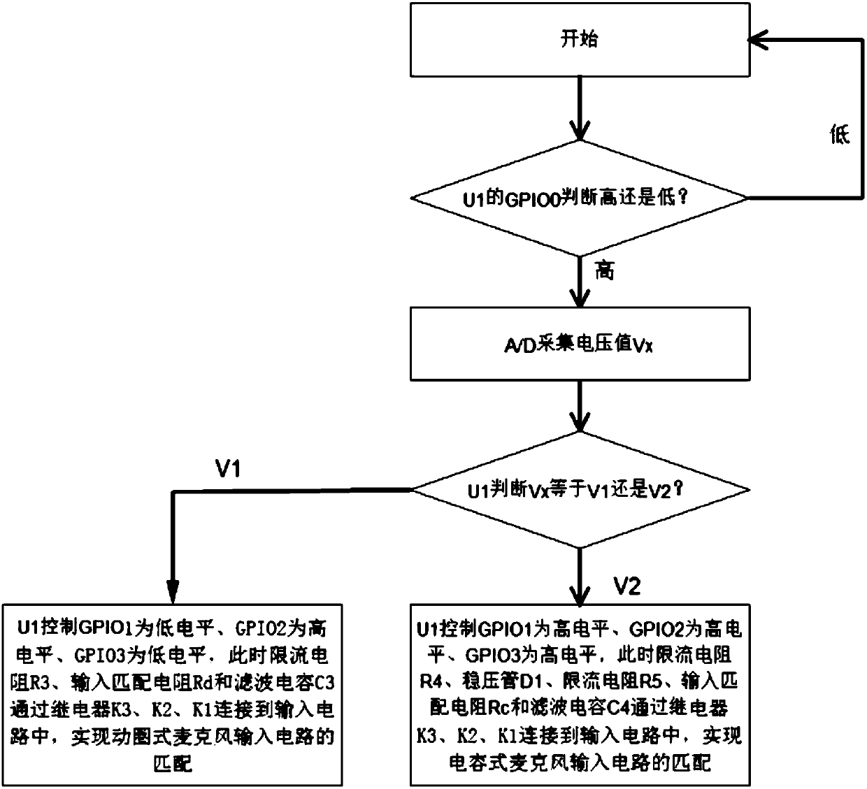
A compatible vehicle-mounted microphone circuit comprises a socket, a detection circuit, a first input matching circuit, a second input matching circuit, a first switching circuit, a second switchingcircuit and a CPU. The input end of the detection circuit is connected with the socket to detect the socket state; the first switching circuit is connected with the second switching circuit to controlthe switching-on or switching-off of the matching of the input circuit; the second switching circuit is connected with the first input matching circuit and the second input matching circuit so as tocontrol access to the first input matching circuit or the second input matching circuit; and the CPU is connected with the output end of the detection circuit, the first switching circuit, the secondswitching circuit and the socket so as to control whether a socket voltage value is acquired or not according to the state of the socket, compare the voltage value with a pre-stored threshold value, judge the type of the microphone and control the first switching circuit and the second switching circuit to act so as to realize matching of the input circuit. The compatible use of the moving-coil microphone and the capacitive microphone can be realized, the circuit is simple, and the cost is low.

Description

technical field [0001] The invention relates to the field of microphone circuits, in particular to a compatible vehicle-mounted microphone circuit. Background technique [0002] In the application of vehicle-mounted multimedia terminal equipment in passenger cars, especially tourist buses, it is generally required that the multimedia terminal equipment needs to have a microphone for calling out. As people diversify their entertainment functions, some customers need to be equipped with dynamic wired microphones. Some customers require a capacitive wired microphone, and the principles of the two microphones are different, so the compatibility of the two microphone input circuits needs to be considered during the circuit design process. [0003] The dynamic microphone uses the principle of electromagnetic induction to convert the sound signal into an electrical signal by cutting the magnetic induction line through the coil in the magnetic field. The condenser microphone, also ...

Claims


Application Information

Patent Timeline
Patent Type & Authority Applications(China)
IPC IPC(8): H04R3/12
CPCH04R3/12H04R2430/00
Inventor 兰伟华汤益明陈远李家祥
Owner XIAMEN YAXON NETWORKS CO LTD
Learn More