Table-tennis pickup machine

A technology for table tennis and pick-up machines, applied to balls, rackets, sports accessories, etc., can solve problems such as impact, low work efficiency, easy soreness in the waist that affects follow-up work, etc., to avoid waist pain, high work efficiency, and easy to take out Effect

Active Publication Date: 2019-07-26
嘉兴市迅程信息技术有限公司
View PDF2 Cites 3 Cited by
  • Summary
  • Abstract
  • Description
  • Claims
  • Application Information

AI Technical Summary

Problems solved by technology

[0003] In order to overcome the shortcoming of low work efficiency due to the fact that the staff needs to bend over to pick up the ball, the waist is prone to soreness over time and affects the follow-up work, and the hand is limited to only pick up one table tennis ball at a time, the technical problem is to provide a table tennis ball that can replace manual work. Pick up balls to avoid backaches affecting follow-up work, and can pick up multiple table tennis balls at a time, a table tennis ball picker with high work efficiency

Method used


Image

  • Table-tennis pickup machine
  • Table-tennis pickup machine
  • Table-tennis pickup machine

Examples


Embodiment 1

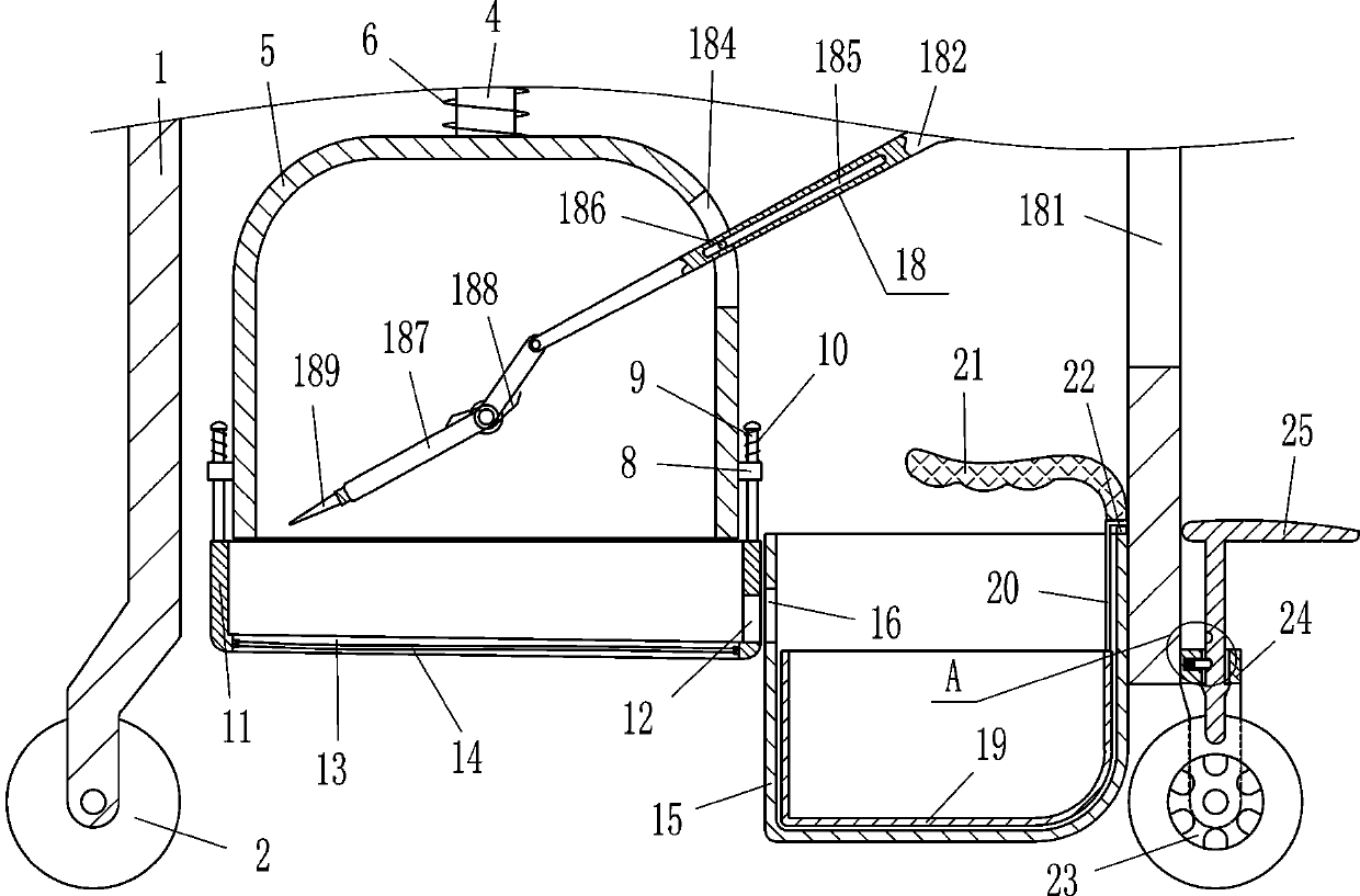
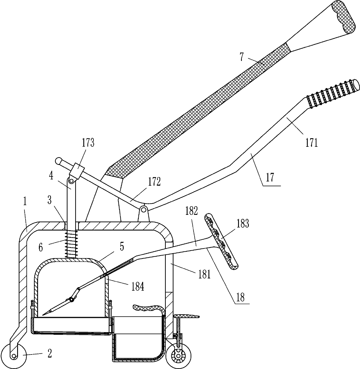
[0022] A table tennis pick-up machine, such as Figure 1-4 As shown, it includes n-shaped frame 1, wheel 2, movable rod 4, frame body 5, first spring 6, push handle 7, first guide sleeve 8, guide rod 9, second spring 10, movable frame 11, elastic belt 14. The collection frame 15 and the driving mechanism 17, the bottom ends of the left and right sides of the n-shaped frame 1 are connected with wheels 2 in a rotating manner, the left side of the top of the n-shaped frame 1 has a first through hole 3 for guiding, and the movable rod 4 Located in the first through hole 3, a drive mechanism 17 is provided between the top of the movable rod 4 and the right side of the outer top of the n-shaped frame 1, the frame body 5 is installed on the bottom end of the movable rod 4, and the first spring 6 is sleeved on the movable rod 4 , one end of the first spring 6 is fixedly connected to the inner top of the n-shaped frame 1, the other end of the first spring 6 is fixedly connected to the ...

Embodiment 2

[0024] A table tennis pick-up machine, such as Figure 1-4As shown, it includes n-shaped frame 1, wheel 2, movable rod 4, frame body 5, first spring 6, push handle 7, first guide sleeve 8, guide rod 9, second spring 10, movable frame 11, elastic belt 14. The collection frame 15 and the driving mechanism 17, the bottom ends of the left and right sides of the n-shaped frame 1 are connected with wheels 2 in a rotating manner, the left side of the top of the n-shaped frame 1 has a first through hole 3 for guiding, and the movable rod 4 Located in the first through hole 3, a drive mechanism 17 is provided between the top of the movable rod 4 and the right side of the outer top of the n-shaped frame 1, the frame body 5 is installed on the bottom end of the movable rod 4, and the first spring 6 is sleeved on the movable rod 4 , one end of the first spring 6 is fixedly connected to the inner top of the n-shaped frame 1, the other end of the first spring 6 is fixedly connected to the o...

Embodiment 3

[0027] A table tennis pick-up machine, such as Figure 1-4 As shown, it includes n-shaped frame 1, wheel 2, movable rod 4, frame body 5, first spring 6, push handle 7, first guide sleeve 8, guide rod 9, second spring 10, movable frame 11, elastic belt 14. The collection frame 15 and the driving mechanism 17, the bottom ends of the left and right sides of the n-shaped frame 1 are connected with wheels 2 in a rotating manner, the left side of the top of the n-shaped frame 1 has a first through hole 3 for guiding, and the movable rod 4 Located in the first through hole 3, a drive mechanism 17 is provided between the top of the movable rod 4 and the right side of the outer top of the n-shaped frame 1, the frame body 5 is installed on the bottom end of the movable rod 4, and the first spring 6 is sleeved on the movable rod 4 , one end of the first spring 6 is fixedly connected to the inner top of the n-shaped frame 1, the other end of the first spring 6 is fixedly connected to the ...


PUM


Abstract

The invention relates to a pickup machine, in particular to a table-tennis pickup machine. The technical aim that the table-tennis pickup machine is capable of replacing manual operation for picking up table tennis, avoiding waist aching pain to influence following work and picking up multiple pieces of table tennis one time and is high in working efficiency. The table-tennis pickup machine comprises a n-type frame, wheels, a movable rod, a frame, a first spring, a pushing handle, first guiding sleeves, guiding rods, second springs, a movable frame, an elastic belt and the like; the wheels arerotationally connected to the bottom ends of the left side and the right side of the n-type frame, and a first through hole with a guiding effect is formed in the left side of the top of the n-type frame. According to the table-tennis pickup machine, a pulling rod is pulled, the elastic belt can move downwards, multiple pieces of table tennis are squeezed into the movable frame, and fall into a collecting frame, persons do not need to continuously stoop to pick up table tennis with the hands, aching pains of the waist are avoided to influence follow-up work, and the working efficiency is alsohigh; through a shifting device, it can be avoided that table tennis in the movable frame is clamped and cannot fall into the collecting frame.

Description

technical field [0001] The invention relates to a picking machine, in particular to a table tennis picking machine. Background technique [0002] In the place where table tennis is played, the trainers use the ball machine to train, but when the trainers hit the table tennis balls and fall to the ground, the staff needs to pick up the table tennis balls. Usually the staff use Picking up the table tennis balls by hand, because the staff need to bend over to pick up the balls, the waist will be sore after a long time, which will affect the follow-up work, and the hand limit can only pick up one table tennis ball at a time, so the work efficiency is low, so people will use a broom to pick up the table tennis balls. Sweep the table tennis balls to a pile, and then use a shovel to scoop up the table tennis balls for collection, which is troublesome to operate. Contents of the invention [0003] In order to overcome the shortcoming of low work efficiency due to the fact that th...

Claims


Application Information

Patent Timeline
Patent Type & Authority Applications(China)
IPC IPC(8): A63B47/02
CPCA63B47/024A63B2102/16
Inventor 任涛涛
Owner 嘉兴市迅程信息技术有限公司
Why Eureka
Try Eureka