Combined type mechanical loading creep age forming device

A technology of creep aging forming and mechanical loading, which is applied in the processing field of metal materials, can solve the problems of large contact stress, difficult mold repair, high cost, etc., and achieves the effects of low production cost, good adaptability and simple structure

Active Publication Date: 2019-07-26
HUNAN UNIV OF SCI & TECH
View PDF12 Cites 10 Cited by
  • Summary
  • Abstract
  • Description
  • Claims
  • Application Information

AI Technical Summary

Problems solved by technology

In the early stage of creep aging forming technology development, components are usually fixed to the mold surface by mechanical loading, which can be mainly divided into two types: lattice type and concave-convex type. Due to the small contact area between bolts and components, the lattice type , resulting in a large contact stress, and the surface of the component is prone to flaws; the concave-convex type is not easy to repair the mold, and the cost is high
CN101518803A discloses a pure bending aging forming die combined with four-point bending and a frame-plate structure. CN102266887A discloses a form-plate type mechanically loaded creep aging forming device. Combining array and concave-convex devices, the lower mold is not easy to repair, and the cost is high

Method used


Image

  • Combined type mechanical loading creep age forming device
  • Combined type mechanical loading creep age forming device
  • Combined type mechanical loading creep age forming device

Examples


Embodiment Construction

[0018] The present invention will be further described below in conjunction with the accompanying drawings.

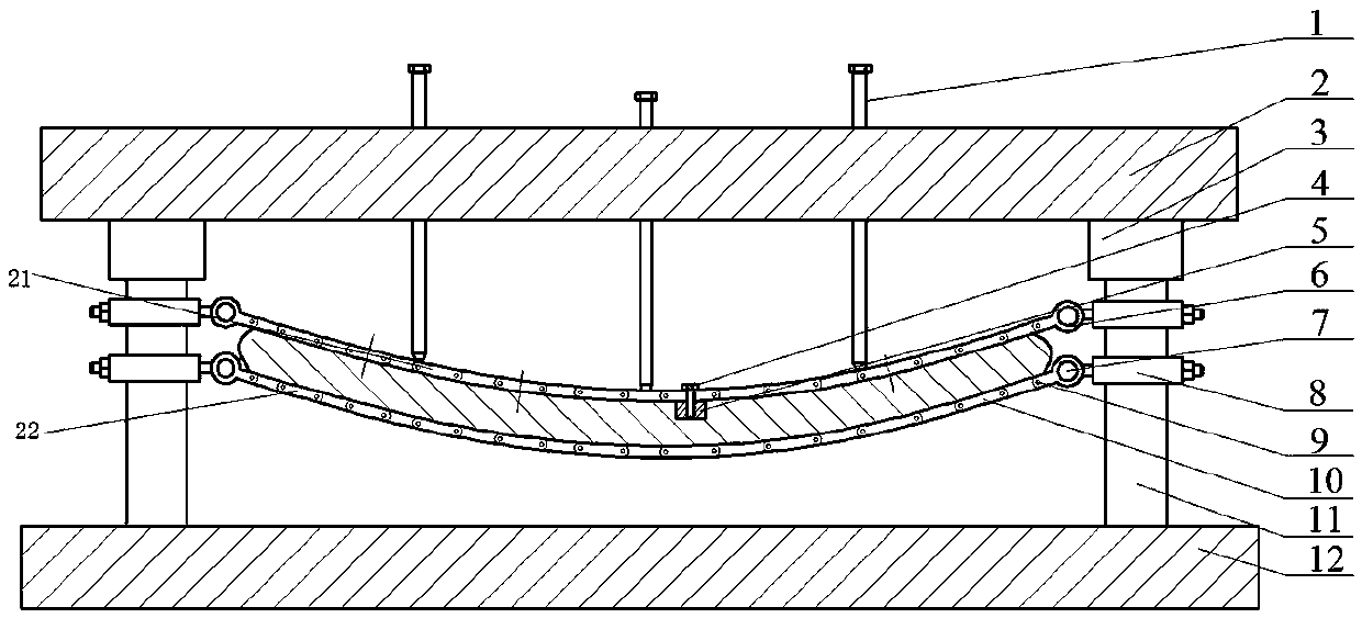
[0019] Such as figure 1 As shown, the present invention includes a loading bolt 1, an upper template 2, a guide sleeve 3, a convex module 5, a movable fixed block 8, a punch 21, a concave mold 22, a lower template 11 and a guide post 12. The upper formwork 2 and the lower formwork 11 are arranged in parallel, the bottom of both sides of the upper formwork 2 are respectively provided with a plurality of guide sleeves 3, and the top surface of the lower formwork 11 is provided with a plurality of guide pillars 12, and the plurality of guide pillars 12 correspond to It is arranged on a plurality of guide sleeves 3 , and the upper ends of the guide pillars 12 are placed in the corresponding guide sleeves 3 to support the upper formwork 2 . The upper template 2 is provided with a plurality of loading bolts 1 , the loading bolts 1 are arranged perpendicular to the upper tem...


PUM


Abstract

The invention discloses a combined type mechanical loading creep age forming device which comprises an upper die plate, loading bolts, a male die and a female die. Two sides of the upper die plate aresupported through multiple stand columns; the multiple loading bolts are arranged on the upper die plate; the lower ends of the loading bolts contact the top surface of the male die; the male die andthe female die are formed by hinging multiple bidirectional shaped plate connecting units; and two sides of the male die and the female die are connected with the stand columns on two sides of the upper die plate. The combined type mechanical loading creep age forming device provided by the invention can flexibly adjust the shapes and the sizes of the curved surfaces of the male die and the female die so as to be suitable for parts with complicated-curvature curved surfaces and conventional single-curvature parts, and suitable for forming small-sized parts and large-sized parts. The combinedtype mechanical loading creep age forming device provided by the invention can be used for correcting a piece to be formed deformed due to resilience, and is simple in structure, low in production cost, and not only suitable for small-batch scientific research tests but also suitable for industrial production.

Description

technical field [0001] The invention belongs to the technical field of metal material processing, and in particular relates to a combined mechanically loaded creep aging forming device. Background technique [0002] The modern aircraft structure is developing towards light weight and integrity, which makes the requirements for the forming technology of aircraft parts continue to increase. Among them, the manufacturing technology of integral panel components with complex shapes and structures has become the core and key of modern aircraft manufacturing. Traditional stretching, roll bending, shot peening, etc. can easily lead to problems such as uneven deformation of components, uneven distribution of internal stress, local damage, etc., thereby reducing the reliability of components. The creep aging forming process integrates the forming-based manufacturing environment and the forming-based heat treatment environment in time and space, so that the metal undergoes slow deforma...

Claims


Application Information

Patent Timeline
Patent Type & Authority Applications(China)
IPC IPC(8): B21D11/20
CPCB21D11/20
Inventor 刘文辉曹平陈宇强唐昌平刘筱赵晨冰卓磊霖
Owner HUNAN UNIV OF SCI & TECH
Why Eureka
Try Eureka