Mechanical equipment circuit binding device

A technology of mechanical equipment and strapping device, which is applied in the direction of metal processing, electrical components, etc., can solve the problems of cumbersome operation, inconvenient use, and inability to effectively tighten the strapping, so as to ensure the tightening effect, reduce the rigid contact, and ensure the appearance sexual effect

Inactive Publication Date: 2019-07-26
CHANGCHUN SUJIAN TECH CO LTD
View PDF0 Cites 0 Cited by
  • Summary
  • Abstract
  • Description
  • Claims
  • Application Information

AI Technical Summary

Problems solved by technology

[0002] Cable ties, also known as cable ties, cable ties, and lock ties, can be divided into nylon cable ties, stainless steel cable ties, and plastic-sprayed stainless steel cable ties according to their materials; there are many types of cable ties according to their functions. , Retractable cable ties, signage cable ties, fixed lock cable ties, bolt-type cable ties, heavy tension cable ties, etc., in the prior art, when manually using the strapping straps, the strapping straps cannot be effectively tightened. The tape is easy to slide on the line and cannot effectively tie the line. It is easy to cause the mechanical line to be scattered and piled up for a long time. It is difficult to find problems during maintenance, inconvenient to use, and cumbersome to operate. For this reason, we propose a mechanical equipment line tie.

Method used


Image

  • Mechanical equipment circuit binding device
  • Mechanical equipment circuit binding device

Examples


Embodiment Construction

[0016] In order to further understand the invention content, characteristics and effects of the present invention, the following embodiments are listed below, and detailed descriptions are as follows in conjunction with the accompanying drawings.

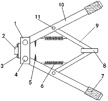
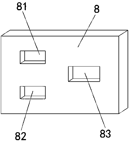
[0017] Combine below Figure 1-2 A detailed description of the mechanical equipment circuit binder of the present invention: a mechanical equipment circuit binder, including a clamp mounting seat 1, a cable tie clamp 2, a blade 5, a return spring 6, a cable tie fixing plate 8 and a manual pressing lever 10. The left side of the clamp mounting base 1 is provided with a cable tie clamp 2, and the cable tie clamp 2 is fixedly connected to the left side of the clamp mounting base 1 through bolts 3. On the clamp mounting base 1 , the lower part is provided with a first connecting shaft 4, the first connecting shaft 4 is connected with a manual pressing rod 10, and the manual pressing rod 10 is rotationally connected with the chuck mounti...


PUM


Abstract

The invention relates to a mechanical equipment circuit binding device. The mechanical equipment circuit binding device comprises a chuck mounting seat, a binding strip chuck, blades, reset springs, abinding strip fixing plate and manual pressing rods, wherein the binding strip chuck is arranged on the left side of the chuck mounting seat, and the binding strip chuck is fixedly connected to the left side face of the chuck mounting seat through bolts. According to the mechanical equipment circuit binding device, the blades are arranged on the inner sides of the ends, close to the chuck mounting seat, of the manual pressing rods, and the blades are meshed with each other after a binding strip is tensioned so that redundant pull strip tail strips can be cut off in time, the attractiveness ofthe binding strip is guaranteed, and other work is not affected or limited space is not occupied; and the binding strip fixing plate is arranged, three clamping holes which are formed in a crossed mode are utilized, and the tail part of the binding strip sequentially passes through the first clamping hole, the second clamping hole and the third clamping hole so that the binding strip can be effectively fixed, the sharp rigid contact is reduced, damage and breakage in the tensioning process are avoided, and the tensioning effect is guaranteed.

Description

technical field [0001] The invention belongs to the technical field of line arrangement, and in particular relates to a line binding device for mechanical equipment. Background technique [0002] Cable ties, also known as cable ties, cable ties, and lock ties, can be divided into nylon cable ties, stainless steel cable ties, and plastic-sprayed stainless steel cable ties according to their materials; there are many types of cable ties according to their functions. , Retractable cable ties, signage cable ties, fixed lock cable ties, bolt-type cable ties, heavy tension cable ties, etc., in the prior art, when manually using the strapping straps, the strapping straps cannot be effectively tightened. The belt is easy to slide on the line and cannot effectively tie the line. It is easy to cause the mechanical line to be scattered and piled up for a long time. It is difficult to find problems during maintenance, inconvenient to use, and cumbersome to operate. For this reason, we p...

Claims


Application Information

Patent Timeline
IPC IPC(8): B26B27/00H02G3/02
CPCB26B27/00H02G3/02
Inventor 张益瑞
Owner CHANGCHUN SUJIAN TECH CO LTD
Why Eureka
Try Eureka