Inhead type flat plate vulcanizing machine

A plate vulcanizing machine, top-mounted technology, applied to other household appliances, household appliances, applications, etc., can solve the problems of hydraulic oil easily dripping and polluting the upper hot plate, affecting the normal use of equipment, polluting equipment and tapes, etc., to achieve security The effect of normal operation of equipment, convenience of equipment maintenance, and reduction of equipment height

Pending Publication Date: 2019-07-26
青岛海琅智能装备有限公司
View PDF1 Cites 3 Cited by
  • Summary
  • Abstract
  • Description
  • Claims
  • Application Information

AI Technical Summary

Problems solved by technology

However, since the pressurized cylinder of the above-mentioned vulcanizer is hung upside down, the hydraulic oil in the cylinder is easy to drip and pollute the hot plate or tape, which affects the use of the equipment. Even if the oil collecting device is installed, it is difficult to completely avoid excessive hydraulic oil or heat During the movement of the plate, the hydraulic oil overflows the oil collecting device and pollutes the upper heating plate or the tape. Therefore, the existing pressurized cylinder top-mounted plate vulcanizing machine has a large pressurized cylinder hydraulic oil that pollutes the equipment and tape, which affects the normal use of the equipment. and tape yield, which is not conducive to the application of equipment

Method used


Image

  • Inhead type flat plate vulcanizing machine
  • Inhead type flat plate vulcanizing machine
  • Inhead type flat plate vulcanizing machine

Examples


Embodiment Construction

[0046] In the following, the present invention will be specifically described through exemplary embodiments. It should be understood, however, that elements, structures and characteristics of one embodiment may be beneficially incorporated in other embodiments without further recitation.

[0047] In the description of the present invention, it should be noted that the orientation or positional relationship indicated by the terms "inner", "outer", "upper", "lower", "front", "rear" etc. are based on the The positional relationship is only for the convenience of describing the present invention and simplifying the description, but does not indicate or imply that the referred device or element must have a specific orientation, be constructed and operated in a specific orientation, and thus should not be construed as limiting the present invention. In addition, the terms "first" and "second" are used for descriptive purposes only, and should not be understood as indicating or imply...


PUM


Abstract

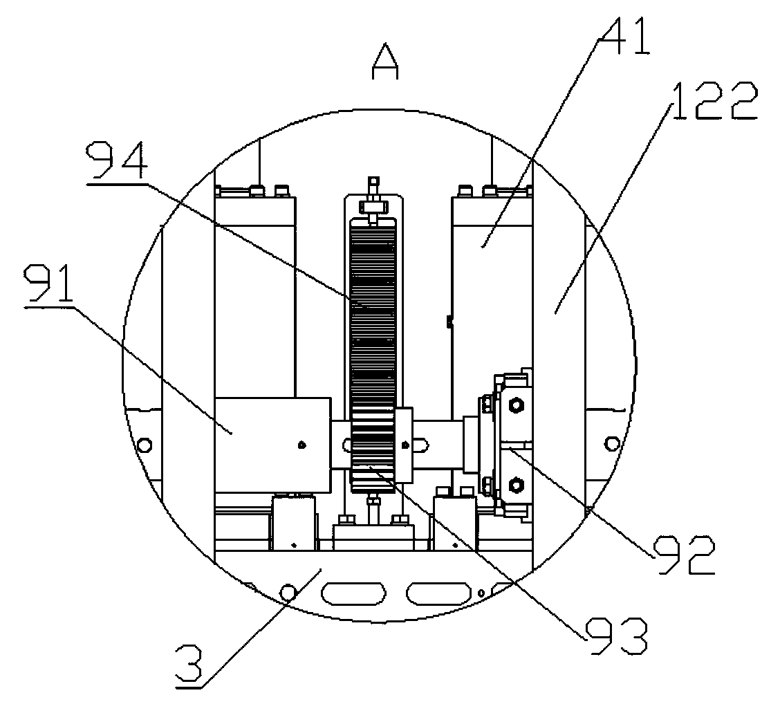
The invention discloses an inhead type flat plate vulcanizing machine. The inhead type flat plate vulcanizing machine comprises a rack and a vulcanizing device; the vulcanizing device comprises a lower heating plate, an upper heating plate, a pressurizing oil cylinder mechanism, a die disassembling and assembling oil cylinder mechanism and a hydraulic control system; the pressurizing oil cylindermechanism comprises a pressurizing oil cylinder which is arranged between the top of the rack and the upper heating plate; a piston rod of the pressurizing oil cylinder is arranged upwards vertically;the upper end part of the piston rod of the pressurizing oil cylinder is fixedly connected with the rack; the bottom of the body of the pressurizing oil cylinder is fixedly installed on the upper surface of the upper heating plate; and the die disassembling and assembling oil cylinder mechanism comprises a die disassembling and assembling oil cylinder which can be used for driving the upper heating plate to move in a direction perpendicular to the upper heating plate. The vulcanizing machine reduces the height of the equipment, guarantees stable application of vulcanizing pressure, reduces the influences of a heat source of the vulcanizing machine on the service life of the pressurizing oil cylinder, can effectively prevent hydraulic oil of the pressurizing oil cylinder from dropping andpolluting the vulcanizing machine and a rubber belt, thereby guaranteeing normal running of the equipment and increasing the finished product rate of the rubber belt.

Description

technical field [0001] The invention relates to the technical field of flat vulcanizing machines, in particular to an overhead flat vulcanizing machine. Background technique [0002] The flat belt plate vulcanizing machine is mainly used for vulcanizing flat belts such as conveyor belts, transmission belts, etc. It has the advantages of high pressure per unit area of ​​the hot plate, reliable operation of the equipment and less maintenance. Its structure mainly includes a frame and a vulcanizing device for vulcanizing flat tapes. The vulcanizing device includes a mold opening and closing mechanism, a pressurizing mechanism, and a cuboid upper and lower heating plate. The main function of the pressurizing mechanism is to provide the pressure required for vulcanization to the adhesive tape clamped between the upper hot plate and the lower hot plate. The pressure is generally generated by a pressurized oil cylinder controlled by a hydraulic control system. At present, commonly...

Claims


Application Information

Patent Timeline
Patent Type & Authority Applications(China)
IPC IPC(8): B29C35/00B29C35/02B29L29/00
CPCB29C35/002B29C35/02B29L2029/00
Inventor 孙友萍陆永高刘鹏石永芝冷于浩
Owner 青岛海琅智能装备有限公司
Why Eureka
Try Eureka