
Multi-section ventilation drag reduction method and device applied for high-speed water surface boat

A drag reduction device and surface craft technology, which is applied to ships, transportation and packaging, hydrodynamic characteristics/hydrostatic characteristics, etc., and can solve problems such as interference with cavitation flow, unstable force, and poor drag reduction effect. , to avoid interference and reduce the effect of gravity drift

Active Publication Date: 2019-07-26
HARBIN ENG UNIV
View PDF6 Cites 10 Cited by
  • Summary
  • Abstract
  • Description
  • Claims
  • Application Information

AI Technical Summary

Problems solved by technology

This arrangement does not take into account the interference of the strut structure on the supercavitation shape, and the pressure distribution near the strut will seriously interfere with the cavitation flow, which will increase the wetted area and lead to poor drag reduction effect
At the same time, due to the lack of development of the current propulsion device, the speed of the flying body cannot meet the expected requirements, and the generated supercavitation is unstable, and the size of the generated cavitation does not meet the purpose requirements.
Moreover, due to the effect of gravity, a single cavitation also has the phenomenon of floating upward, resulting in uneven wetting of the hull and unstable force
Make the dynamic stability of the whole vehicle become a huge problem

Method used


Image

  • Multi-section ventilation drag reduction method and device applied for high-speed water surface boat
  • Multi-section ventilation drag reduction method and device applied for high-speed water surface boat
  • Multi-section ventilation drag reduction method and device applied for high-speed water surface boat

Examples


Embodiment 1

[0040] The situation of arranging 3 annular cavitators at a speed of 40 knots will be described in detail.

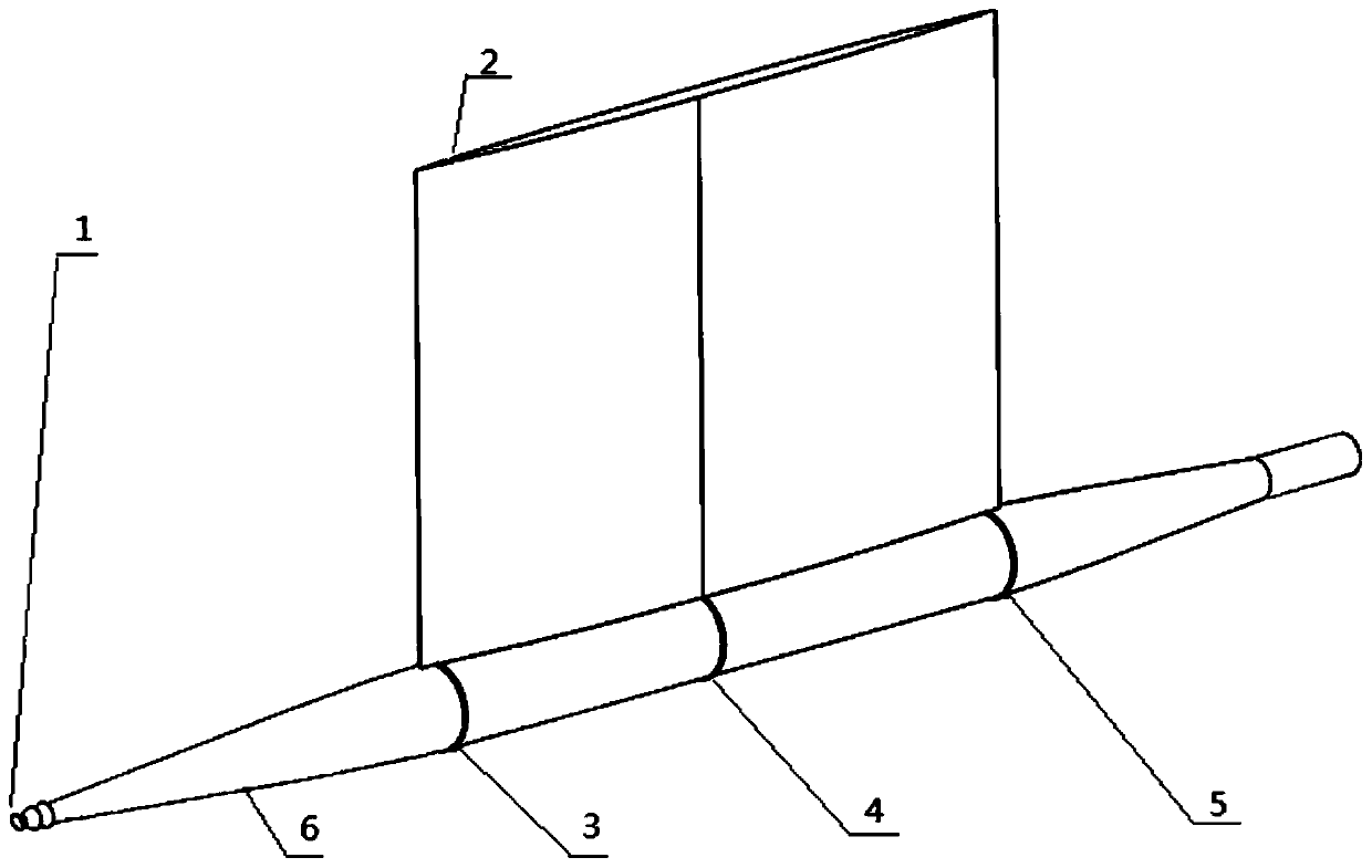
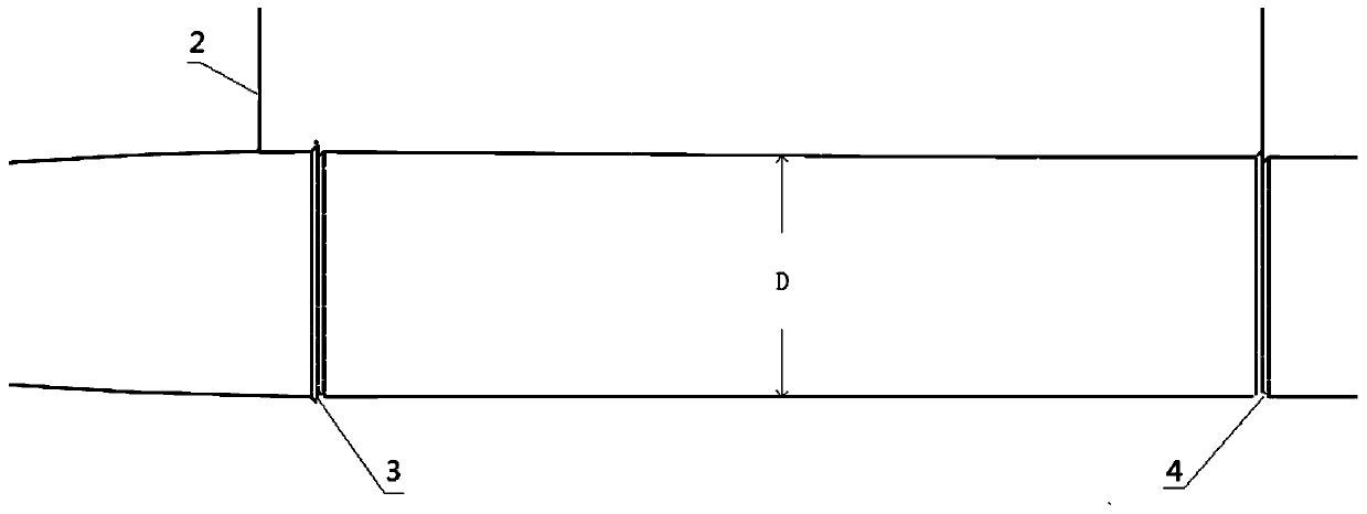
[0041] The disc cavitator (1) and the annular cavitator (3), (4) and (5) generate four supercavitation bubbles connected in series, respectively wrapping the part between itself and the next cavitator. The annular cavitator (3) is arranged a short distance behind the front edge of the strut structure (2). Prevent the strut structure (2) from interfering with the cavitation generated by the annular cavitator. Furthermore, the wetted area is reduced, the interference of the pillars on the stability of the supercavitation is reduced, and the purpose of reducing resistance is achieved. The pillar structure (2) is arranged on the cylindrical section of the submerged body (6), which is convenient for production and processing. The gas is transported to each exhaust hole (9) through the air-inducing groove (8), and then flows out along the air guide shoe (7) on the back flow...


PUM


Abstract

The invention discloses a multi-section ventilation drag reduction method and device applied for a high-speed water surface boat. The device includes a disc cavitator, a pillar structure, a ring-shaped cavitator, a diving body, an air guiding tile, an air inlet groove, and an air exhausting hole, wherein an axis of the disc cavitator is downward inclined, the ring-shaped cavitator is arranged behind the front edge of the pillar structure, the pillar structure is arranged in the middle section of the diving body, a ventilation device is arranged behind the ring-shaped cavitator, and an includedangle between the incident flow surface of the ring-shaped cavitator and the incoming flow direction is 45 degrees. According to the multi-section ventilation drag reduction method and device appliedfor the high-speed water surface boat, a certain attack angle is arranged on the axis of the head part ring-shaped cavitator, and influence of the partial gravity effect on a cavitation form can be offset; and a great deal of cavitator is adopted, interference of a pillar on the cavitation is avoided, and the effect of adverse factors such as gravity floating and instability of ventilation supercavitation on the cavitation is weakened.

Description

technical field [0001] The invention relates to a ventilation method and a device for a surface boat, in particular to a multi-section ventilation drag reduction method and a device for a high-speed surface boat, and belongs to the technical field of ship application. Background technique [0002] Small waterplane area catamarans have good seakeeping that is difficult for conventional ships to achieve. However, due to the large wetted surface area, frictional resistance accounts for a large proportion of the total resistance and increases quadratically with speed. However, the small waterplane area catamaran has a torpedo-type underwater submersible structure, and the supercavitation drag reduction technology has a very obvious effect in torpedo drag reduction. Therefore, in order to increase the speed of the vehicle and improve the performance of the vehicle , the supercavitation drag reduction technology can be applied to the small waterplane area catamaran. [0003] The ...

Claims


Application Information

Patent Timeline
IPC IPC(8): B63B1/38
CPCB63B1/38B63B2001/382B63B2001/387Y02T70/10
Inventor 安海任航高文杰孙鹏阎朝一尹瑰巧
Owner HARBIN ENG UNIV
Learn More