Control plane cavitation effect suppression device

A cavitation effect and suppressing device technology, applied in the field of ship rudder, can solve problems such as increased resistance and damage, and achieve the effects of increasing the critical Reynolds number, extending the laminar flow area, and reducing the separation area

Pending Publication Date: 2019-07-26
HARBIN ENG UNIV
View PDF11 Cites 1 Cited by
  • Summary
  • Abstract
  • Description
  • Claims
  • Application Information

AI Technical Summary

Problems solved by technology

In addition to being damaged by the impact, the surface of the object there will also lead to a significant increase in resistance

Method used


Image

  • Control plane cavitation effect suppression device
  • Control plane cavitation effect suppression device
  • Control plane cavitation effect suppression device

Examples


Embodiment Construction

[0023] The following examples describe the present invention in more detail.

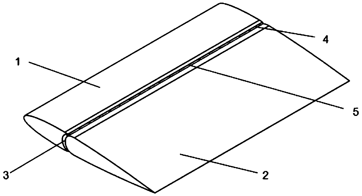
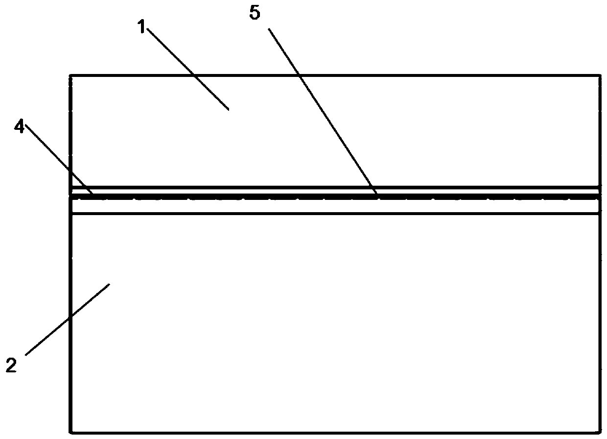
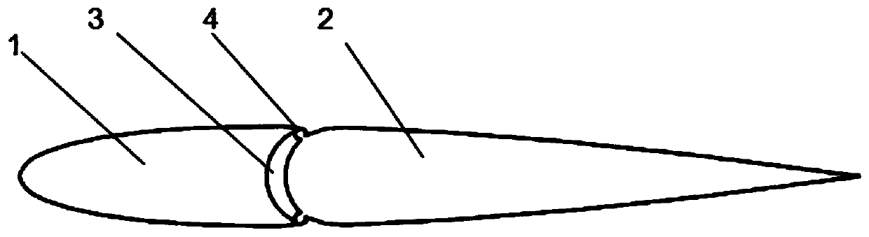
[0024] combine Figure 1 to Figure 6 The rudder surface cavitation suppression device of the present invention comprises an air pump 7 and a vent pipe 4, the air pump is installed inside the hull, the vent pipe is positioned at the gap between the rudder arm and the rudder blade, and the upper end of the vent pipe is fixed on the stern board 8 And communicate with the air pump, the lower end of the ventilation pipe is closed. The rudder arm 1 is connected to the rudder blade 2 and the rudder blade 2 can be rotated. The air pipe 4 is located in the gap 3 between the rudder arm 1 and the rudder blade 2. The two air pipes 4 are placed symmetrically with respect to the chord length, and the air holes 5 are evenly distributed in the air vents. On the trachea 4, the air holes 5 are distributed along the length and blow air to the rudder surface. The air pump 7 is located above the stern plate 8. The air ...


PUM


Abstract

The invention provides a control plane cavitation effect suppression device, including an air pump and a breather pipe. The air pump is arranged in a ship body and the breather pipe is located in thegap between a rudder horn and a rudder blade. The upper end of the breather pipe is fixed on a transom plate and communicates with the air pump. The lower end of the breather pipe is closed, and air holes for blowing air to the surface of a rudder blade are formed in the breather pipe. Through blowing to the control plane from the gap, control plane pressure increases and a cavitation effect is not prone to being produced. Kinetic energy of fluid near a boundary layer separation point can be increased to move the separation point back and decrease a separation area to achieve the effect of reducing form resistance. A laminar region can be extended, a critical Reynolds number can be increased and viscous resistance can be dramatically reduced under the critical Reynolds number.

Description

technical field [0001] The invention relates to a ship rudder, in particular to a cavitation effect suppressing device. Background technique [0002] Cavitation occurs on the basis of a continuous breakdown of the liquid medium and is the result of a drop in pressure. When the pressure at a certain point in the liquid drops below a certain critical pressure, the liquid vaporizes, first microscopically, then macroscopically small bubbles, and then converging inside the liquid or at the interface between the liquid and the solid to form larger vapor and gas bubbles. Cavities of gas are called cavitations. The generation, development and collapse process of cavitation is called cavitation phenomenon. [0003] As the cavitation occurs, the bubbles flow downstream. Generally speaking, the pressure around the cavitation rises again, and the cavitation tends to disappear. However, because the cavitation is generated suddenly, the rushing hydraulic force will cause the bubbles to...

Claims


Application Information

Patent Timeline
Patent Type & Authority Applications(China)
IPC IPC(8): B63H25/38B63B1/38
CPCB63B1/38B63B2001/387B63H25/38Y02T70/10
Inventor 胡健赵旺毛翼轩陈崇格张禹为王雅楠王子斌
Owner HARBIN ENG UNIV
Why Eureka
Try Eureka