Glass positioning device

A positioning device and glass technology, applied in glass cutting devices, glass manufacturing equipment, manufacturing tools, etc., can solve the problems of time-consuming manual positioning, large changes in cutting size, inability to improve production efficiency and product quality, etc.

Pending Publication Date: 2019-07-26
蚌埠朝阳玻璃机械有限公司
View PDF0 Cites 0 Cited by
  • Summary
  • Abstract
  • Description
  • Claims
  • Application Information

AI Technical Summary

Problems solved by technology

The fully automatic laminated glass cutting machine can cut out various shapes of glass, but the existing fully automatic laminated glass cutting machines use manual positioning, resulting in inaccurate cut

Method used


Image

  • Glass positioning device
  • Glass positioning device
  • Glass positioning device

Examples


Embodiment Construction

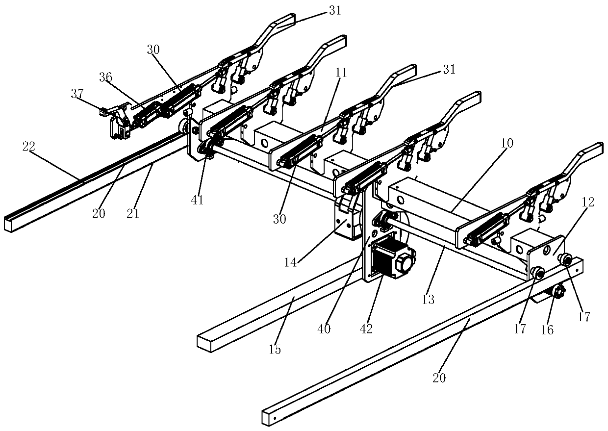
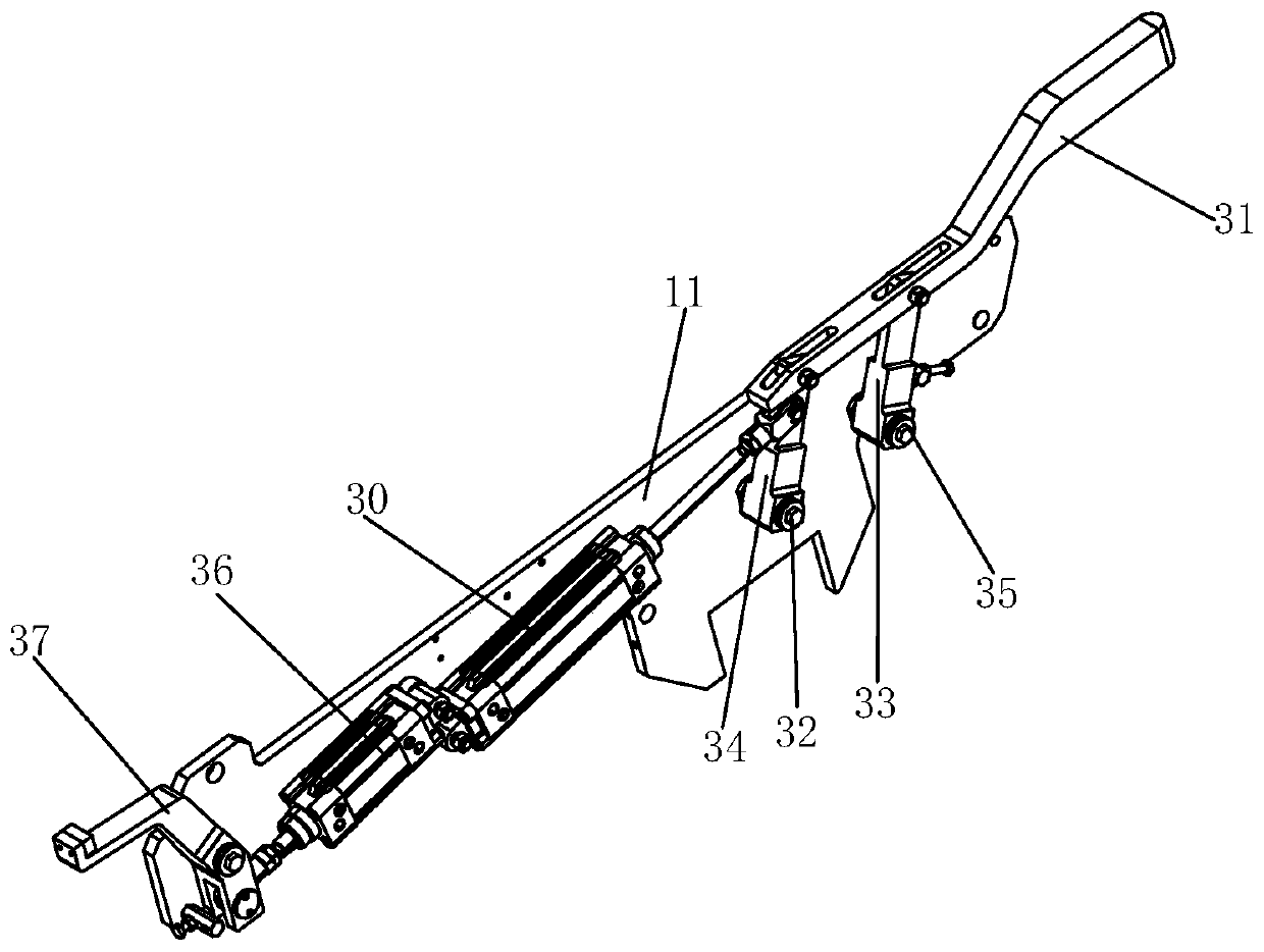
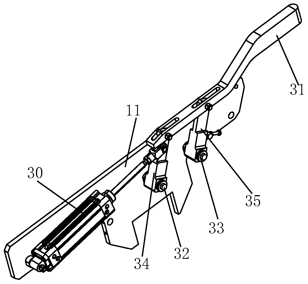
[0017] combined with Figure 1~5 The present invention is further described:

[0018] A glass positioning device, comprising a crossbeam 10, a mounting plate 11 is vertically fixed on the length direction of the crossbeam 10, and a fixing plate 12 is vertically connected to the two ends of the crossbeam 10 downward, and one of the fixing plates 12 There is a rotating shaft 13 connected in rotation, and guide rails 20 are arranged below the two ends of the beam 10, and the guide rail 20 is vertically arranged with the beam 10. The rotating shaft 13 is connected with the driving device, and the rotating shaft 13 is connected to the guide rail. 20 forms a sliding fit, and the plate surface of the mounting plate 11 is provided with a driving cylinder 130, and the telescopic rod of the driving cylinder 130 is connected with the positioning rod 31, and the positioning rod 11 is opposite to the mounting plate 11. The face extends out.

[0019] In the above technical solution, the g...


PUM


Abstract

The invention discloses a glass positioning device. The glass positioning device comprises a crossbeam and is characterized in that a mounting plate is vertically fixed to the length direction of thecrossbeam, fixing plates are downwardly vertically connected to two ends of the crossbeam, a rotary shaft is rotatably connected between the fixing plates, guide rails are arranged below two ends of the crossbeam, the guide rails are vertical to the crossbeam, the rotary shaft is connected with a drive device, the rotary shaft is in slide fit with the guide rails, a first drive air cylinder is arranged on the surface of the mounting plate, the telescoping rod of the first drive air cylinder is connected with a first positioning rod, the first positioning rod extends out relative to the surfaceof the mounting plate, the drive device is connected with the rotary shaft and drives the rotary shaft to slide along the guide rails to achieve the transverse displacement of the positioning device,the firs drive air cylinder drives the first positioning rod to shift vertically, and the outer end of the first positioning rod contacts with glass to apply pressure so as to position the glass. Theglass positioning device adopting an automatic mechanical control manner is high in precision and work efficiency.

Description

technical field [0001] The invention belongs to a laminated glass positioning device, in particular to a glass positioning device. Background technique [0002] Fully automatic laminated glass cutting machine is a processing machine specially used for laminated glass processing and blanking. The fully automatic laminated glass cutting machine can cut out various shapes of glass, but the existing fully automatic laminated glass cutting machines use manual positioning, resulting in inaccurate cutting glass size and large changes in cutting size. , and the process of manual positioning is time-consuming, resulting in low cutting efficiency, unable to improve production efficiency and product quality. Contents of the invention [0003] The object of the present invention is to provide a glass positioning device, which uses mechanized control to position and fix the glass to improve cutting efficiency and product quality. [0004] In order to achieve the above object, the pre...

Claims


Application Information

Patent Timeline
IPC IPC(8): C03B33/03C03B33/07
CPCC03B33/03C03B33/07
Inventor 苏东坡
Owner 蚌埠朝阳玻璃机械有限公司
Why Eureka
Try Eureka