Heat exchange device

A technology of heat exchange device and heat exchange tube, which is applied in the direction of heat exchanger type, heat exchanger shell, indirect heat exchanger, etc., and can solve the problem of low heat exchange efficiency of shell side fluid, low utilization rate of Solve the problems of slow flow rate of process fluid and achieve the effects of simple structure, easy processing and improved heat exchange efficiency

Pending Publication Date: 2019-07-26
TAIZHOU SUPERVISION & INSPECTION CENT OF SPECIAL EQUIP
View PDF2 Cites 0 Cited by
  • Summary
  • Abstract
  • Description
  • Claims
  • Application Information

AI Technical Summary

Problems solved by technology

Although the shell-side fluid passes through the baffle to form a turbulent flow around the shell flow channel, which improves the heat exchange efficiency to a certain extent, however, because the shell-side fluid always only flows around the axis of the shell, the shell-side fluid is close to the The part of the heat exchange tube is always in contact with the heat exchange tube, making its temperature close to the temperature of the heat exchange tube, resulting in a decrease in heat exchange efficiency, while the part of the shell side fluid far aw

Method used


Image

  • Heat exchange device
  • Heat exchange device
  • Heat exchange device

Examples


Embodiment Construction

[0027] The following are specific embodiments of the present invention and in conjunction with the accompanying drawings, the technical solutions of the present invention are further described, but the present invention is not limited to these embodiments.

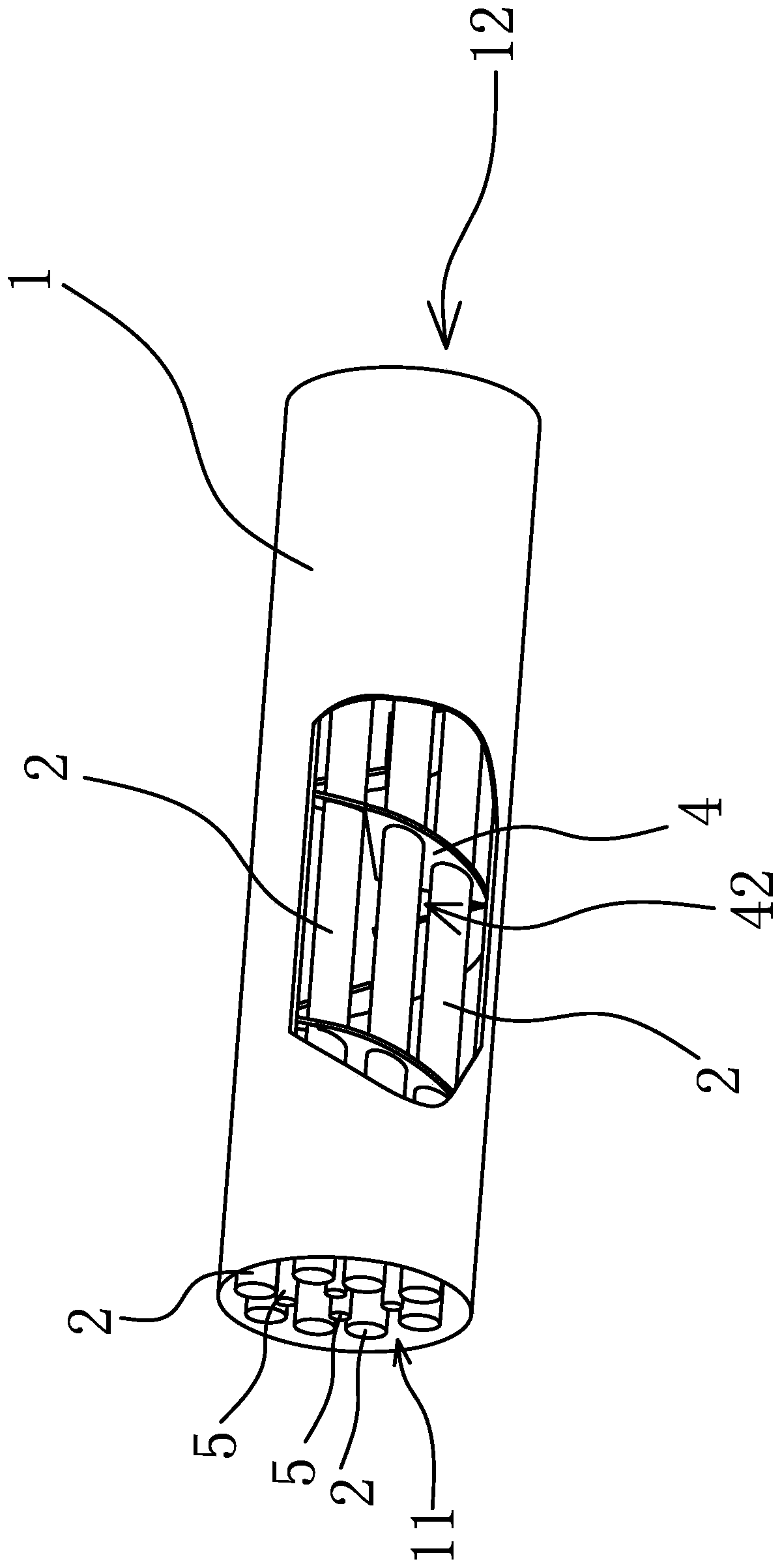
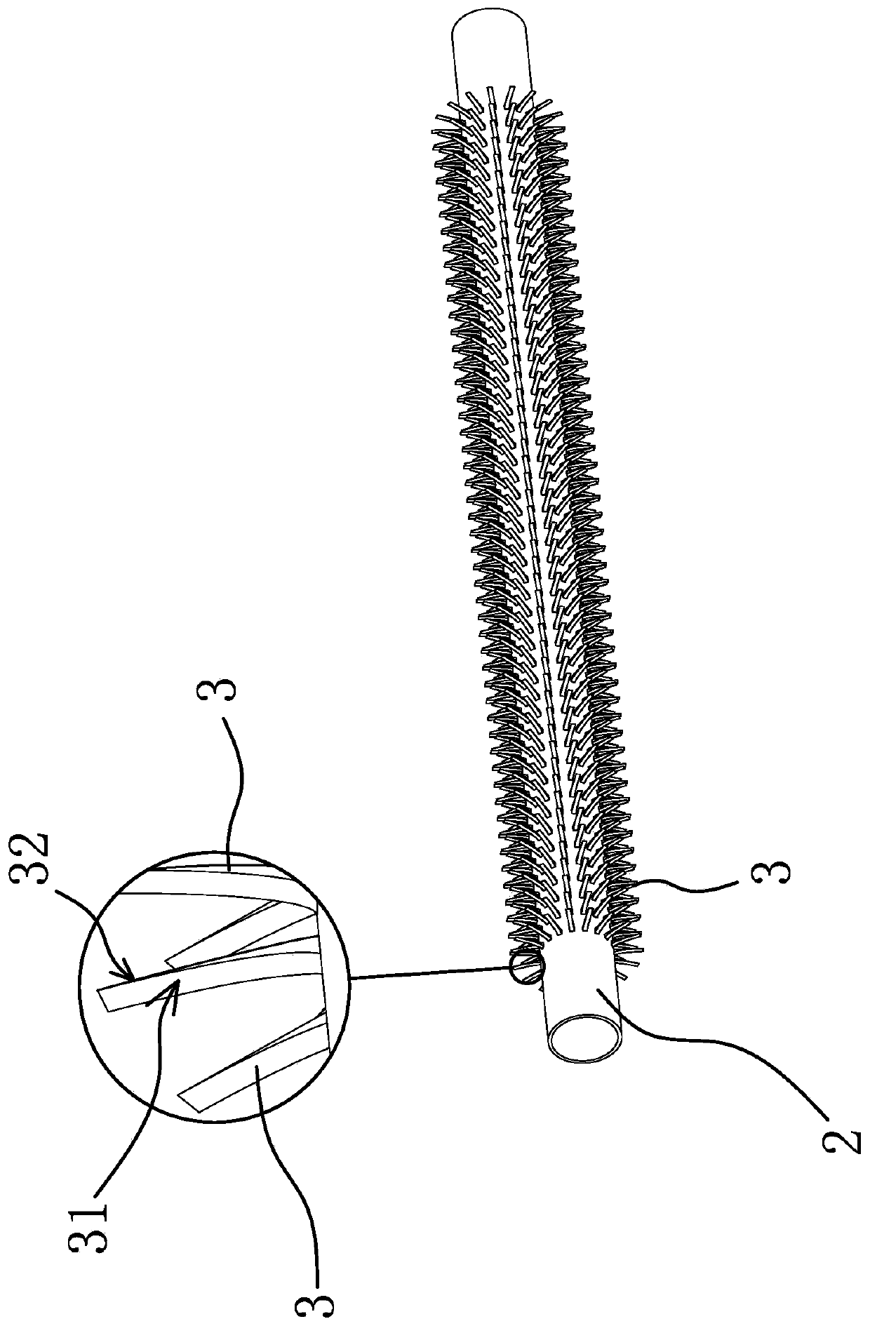
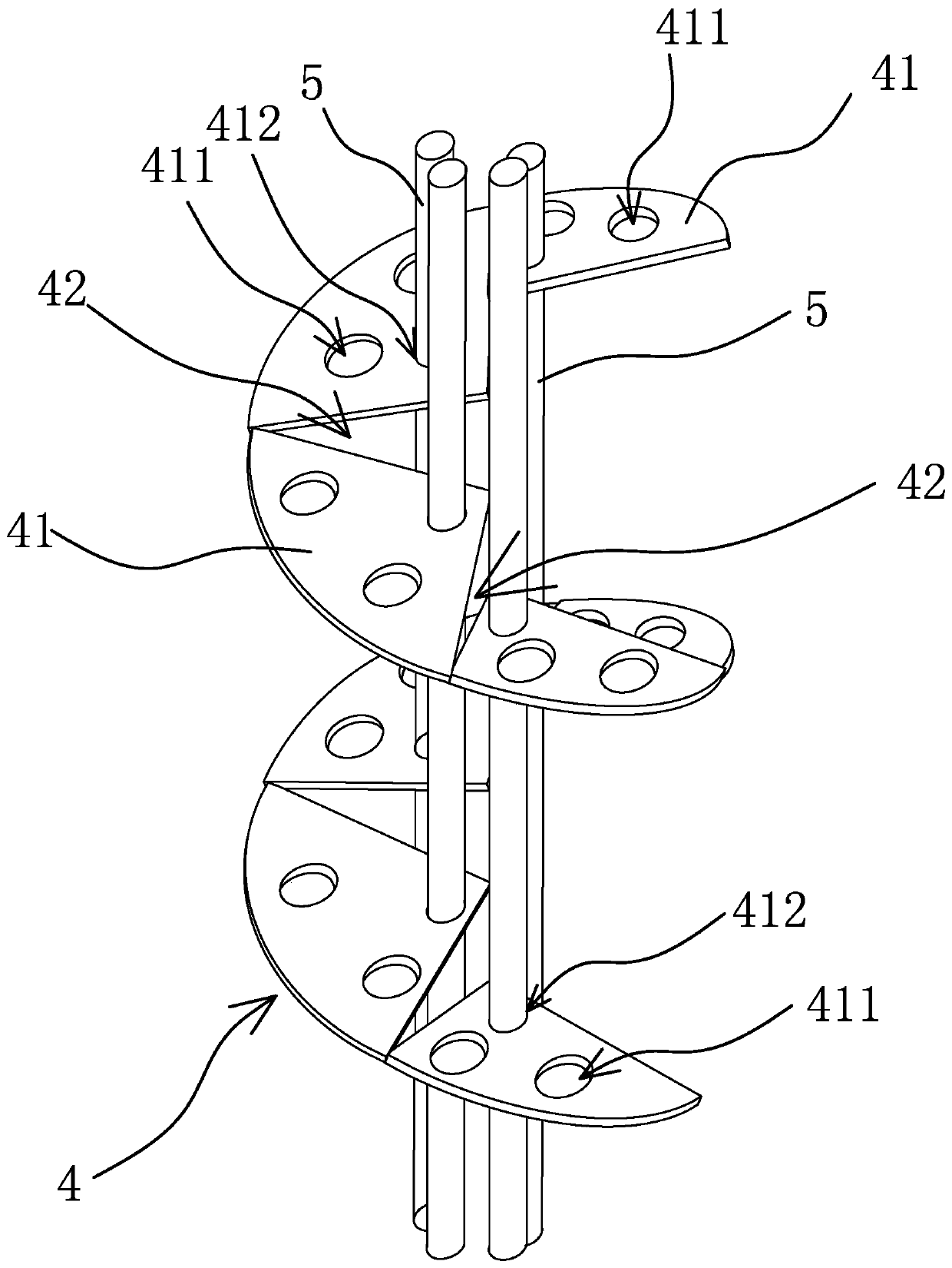
[0028] A heat exchange device such as figure 1 , figure 2 As shown, it includes a shell 1, a baffle plate 4 and a number of heat exchange tubes 2, wherein the shell 1 is cylindrical, one end of the shell 1 has a shell-side fluid inlet 11 and the other end has a shell-side fluid outlet 12, folded The flow plate 4 is spirally arranged in the casing 1 along the length direction of the casing 1, and the heat exchange tube 2 is also arranged in the casing 1 along the length direction of the casing 1. Fins 3, fins 3 have guide surfaces 31 that keep the shell-side fluid away from the heat pipe and form disturbances, and the baffle plate 4 is provided with a plurality of baffles at intervals along its extending direction for the...


PUM

PropertyMeasurementUnit
Angleaaaaaaaaaa

Abstract

The invention provides a heat exchange device and belongs to the technical field of mechanical heat exchange equipment. Through the heat exchange device, the problem that an existing heat exchange device is low in heat exchange efficiency is solved. The heat exchange device comprises a shell, heat exchange tubes arranged in the shell in the length direction and a baffle plate spirally arranged inthe shell in the length direction. One end of the shell is provided with a shell pass fluid inlet, and the other end of the shell is provided with a shell pass fluid outlet. The outer sidewalls of theheat exchange tubes are provided with a plurality of fins. The heat exchange tubes are distributed around the axial line of the shell at intervals. The fins are in a strip shape. The side, facing theshell pass fluid inlet, of each fin is provided with a flow guide surface used for enable shell pass fluid to flow far away from the heat exchange tubes. The baffle plate is provided with baffling ports in the extension direction of the baffle plate at intervals, and the baffling ports get close to the axial line of the shell and allow the shell pass fluid to pass through. The heat exchange device can enable the shell pass fluid to form a radial whirl, so that the shell pass fluid makes more sufficient contact with the heat exchange tubes, the heat exchange efficiency is higher, and the heatexchange effect is better.

Description

technical field [0001] The invention belongs to the technical field of heat exchange equipment, and relates to a shell-and-tube heat exchange device. Background technique [0002] The heat exchange device is an energy-saving device that realizes heat transfer between materials between two or more fluids at different temperatures, so that heat is transferred from a fluid with a higher temperature to a fluid with a lower temperature, so that the temperature of the fluid reaches the process specification To meet the needs, it is also one of the main equipment to improve energy utilization, mainly used in petroleum, chemical, HVAC and other industries. [0003] Heat exchange devices are mainly divided into three categories: partition type, hybrid type and heat storage type. Among them, the shell-and-tube heat exchanger in the partition type has a simple structure, low cost, wide fluid cross-section, easy cleaning of scale, and a wide range of applications. It is the most widely...

Claims


Application Information

Patent Timeline
IPC IPC(8): F28D7/16F28F1/12F28F9/22
CPCF28D7/1623F28F1/124F28F9/22F28F2009/228
Inventor 马刚金仲平元海荣顾荣见李隆骏许林滔胡家扬陈灵江
Owner TAIZHOU SUPERVISION & INSPECTION CENT OF SPECIAL EQUIP
Why Eureka
Try Eureka