Coupling dispensing system and coupling dispensing method
A technology of coupling points and coupling devices, which is applied in the field of coupling dispensing systems, can solve the problems of increased possibility of device coupling surface failure, high coupling difficulty, and poor device consistency, so as to improve efficiency, accuracy, and consistency. The effect of heat reduction
- Summary
- Abstract
- Description
- Claims
- Application Information
AI Technical Summary
Problems solved by technology
Method used
Image
Examples
Embodiment 1
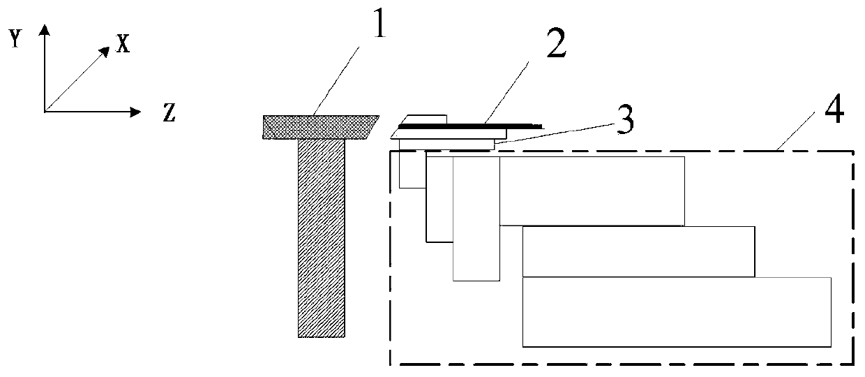
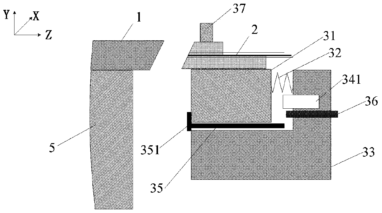
[0067] refer to figure 1 and figure 2 , an automatic coupling device for a coupling dispensing system provided in this embodiment, the automatic coupling device is used to couple the device to be coupled 1 and the optical fiber 2, the automatic coupling device includes: a clamping mechanism 3 and an adjusting mechanism 4, the The clamping mechanism 3 is arranged on the adjusting mechanism 4 .
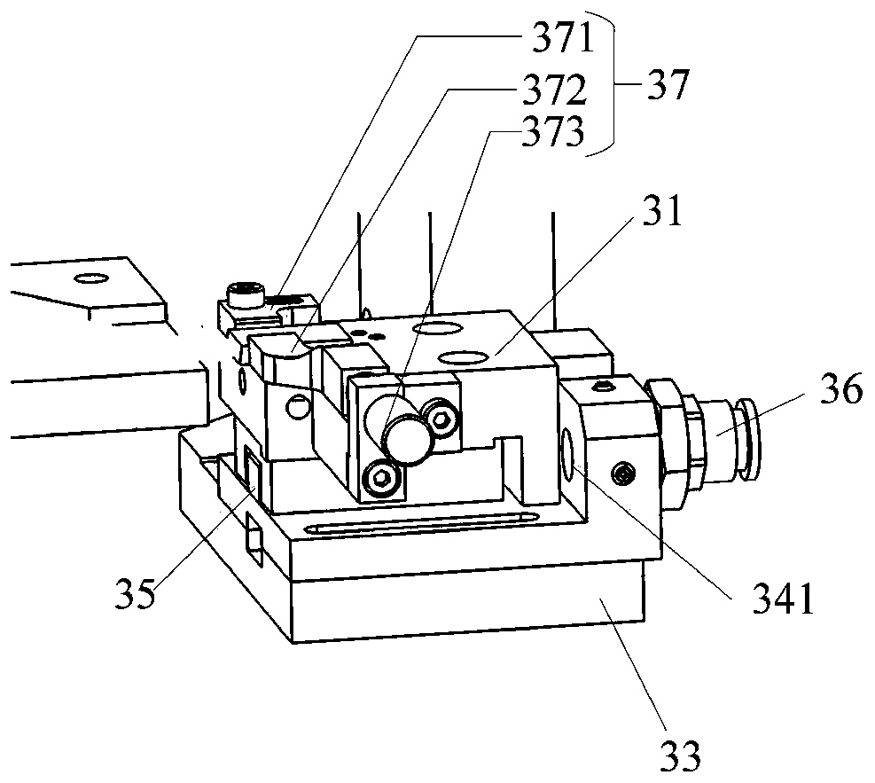
[0068] In this embodiment, the clamping mechanism 3 includes a sliding platform 31 and an elastic member 32 , one end of the elastic member 32 is connected to the sliding platform 31 . Wherein, the elastic member 32 can be a spring, and the elastic force of the spring should not be too large, otherwise it will cause edge collapse of the device 1 to be coupled. In an optional embodiment, the maximum load of the spring is 4N, and the spring constant is greater than 1.0N / mm. In the actual design process, the friction force and other factors when the slide table 31 slides can be consider...
Embodiment 2
[0109] Different from Embodiment 1, the automatic coupling device coupled with the dispensing system provided in this embodiment has another optional solution, which detects the compression state of the elastic member 32 so that the adjustment mechanism 4 can adjust the posture of the clamping mechanism 3 . Such as Figure 15 As shown, the clamping mechanism 3 also includes a pressure sensor 342, the pressure sensor 342 is arranged on the base 33, and the other end of the elastic member 32 is connected to the pressure sensor 342; the pressure sensor 342 It is used to detect changes in the elastic force of the elastic member 32 to trigger the adjustment mechanism 4 to adjust the posture of the clamping mechanism 3 .
[0110] In this embodiment, the pressure sensor 342 is used to detect the change of the elastic force of the elastic member 32 to determine the compression state of the elastic member 32 and determine the sliding table 31 (such as Figure 15 Shown, the distance be...
Embodiment 3
[0116] An embodiment of the present invention provides a coupling dispensing method, which is applicable to the coupling dispensing system in the above-mentioned embodiment 1 or embodiment 2.
[0117] Such as Figure 17 As shown, the coupling dispensing method of the present embodiment includes the following steps:
[0118] Step S10: Clamp the optical fiber on the clamping mechanism, and fix the device to be coupled on the fixed platform.
[0119] Step S20: adjusting the posture of the clamping mechanism through an adjusting mechanism, and detecting the compression state of the elastic member, so that the end face of the optical fiber is parallel to the end face of the device to be coupled.
[0120] Step S30: Dispensing glue in the side direction on the coupling surface between the optical fiber and the device to be coupled.
[0121] In a specific application scenario, the sensor acquires the change of the compression state of the elastic member to monitor the contact state ...
PUM
 Abstract
Description
Claims
Application Information
 - R&D
- Intellectual Property
- Life Sciences
- Materials
- Tech Scout
- Unparalleled Data Quality
- Higher Quality Content
- 60% Fewer Hallucinations
Browse by: Latest US Patents, China's latest patents, Technical Efficacy Thesaurus, Application Domain, Technology Topic, Popular Technical Reports.
© 2025 PatSnap. All rights reserved.Legal|Privacy policy|Modern Slavery Act Transparency Statement|Sitemap|About US| Contact US: help@patsnap.com


